Back in October I purchased a standalone Z-2300 subwoofer on eBay, knowing I could build a DIY remote control pod based on my working Z-2300 set. I disassembled my original remote and deciphered the pinout in a matter of hours. A board was sent off to BatchPCB the next day; two weeks later, I posted this video on YouTube:
Since then, I’ve received dozens of messages from fellow Z-2300 owners, all asking for more information.
Here’s the deal: It would be unethical of me to release the schematic and/or circuit board for public usage, and quite possibly a breach of Logitech’s intellectual property. There are no copyright, trademark, or patent markings on the Z-2300 speaker set or the control pod’s circuit board. However, a Logitech Product Team member at the Logitech message board writes:
“The wiring diagram is not a public document.“
This is understandable—no company publicly releases schematics for their products, and definitely does not allow for others to profit from the company’s products/services. As an engineer, I wholeheartedly respect that.
What is bothersome is Logitech’s backwards policy on replacement parts. I’ve owned my Z-2300 set since late 2005. The volume control has always exhibited terrible channel balance at low volumes. This is caused by differences in the left and right potentiometer gangs, which are pronounced at the lower and upper thresholds of rotation. Such tolerance errors are common amongst dual-ganged pots. There are two fixes: 1) Replace the potentiometer and hope for less error, or 2) Implement attenuation circuitry at the audio input (series resistors), such that the maximum counter-clockwise position of the potentiometer is avoided. I could’ve fixed this imbalance myself. Instead, it was easier to raise the volume on the pod and decrease volume at the PC. Anyway, I called Logitech’s support line one day to see about the prospect of purchasing a replacement remote control. After explaining the annoyance, I was kindly told that Logitech could send me a completely new Z-2300 set for free. Not even a shipping charge. What?! I was willing to shell out cash for a replacement part, and here they were offering to send me a $200 speaker set on their bill.
It turns out this is how Logitech’s warranty works. Rather than repair a faulty device or send out (or sell) replacement parts, they prefer to give away brand new products. I can see how the cost of labor for repairs could be less than profitable, but surely it would be cheaper to send out small replacement parts rather than entire product sets. The Z-2300’s remote control cannot be worth more than $10 in parts—probably much less considering they’re mass produced. Although fantastic for customer service, this approach to repairs is incredibly wasteful. Logitech is a fantastic company, and I was appreciative of their offer, but I declined. I did not need or want a second Z-2300 set (at the time). I was just nitpicking…
Logitech’s wasteful policy affects products besides their Z-2300. A few eBay sellers offer hand-made audio interface cables for the Z-5500, which bypass its digital remote control. These $5-$10 contraptions sell for ridiculous prices ($45-$80). Considering that there are no replacement parts to be sold, this is a clear case of demand outweighing supply. So, the question is, why on Earth doesn’t Logitech sell replacement parts? It would be profitable!
With all of that said, I would very much like to release the information I have unearthed. From the messages I’ve received, it is clear that plenty of people with out-of-warranty Z-2300’s are interested in purchasing Logitech replacement parts. Several people have lost their control pods during moves; some have dropped or otherwise broken them; some want to tap into the circuitry for unique modifications (often multiple subwoofers…); some, like me, just wanted a better performing volume control.
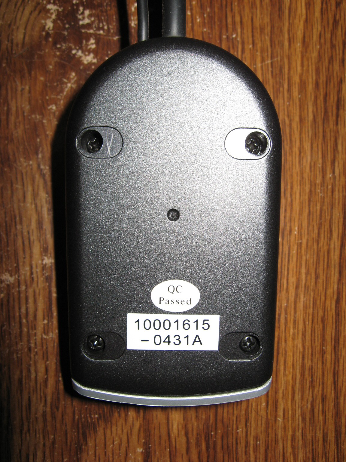
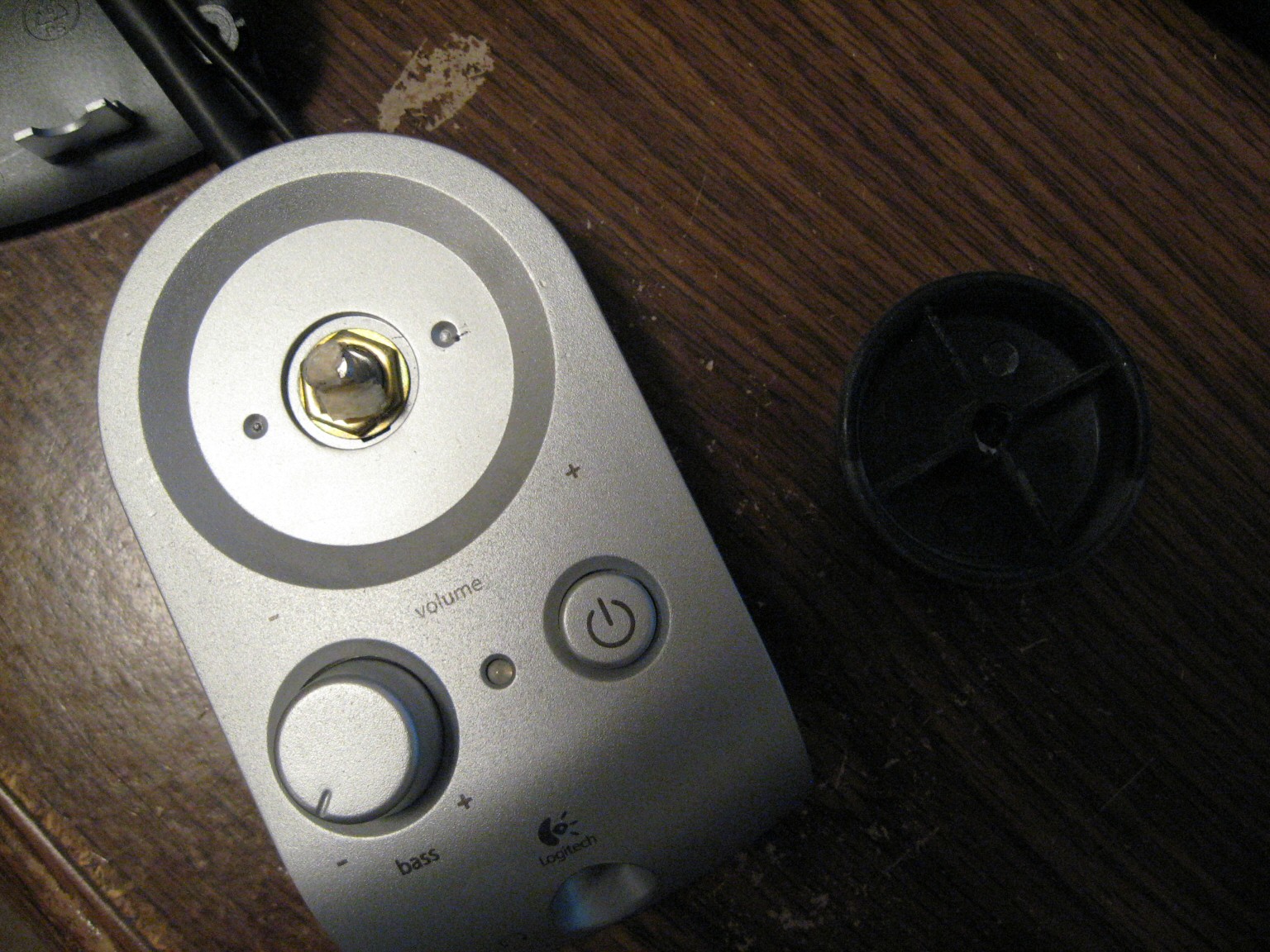
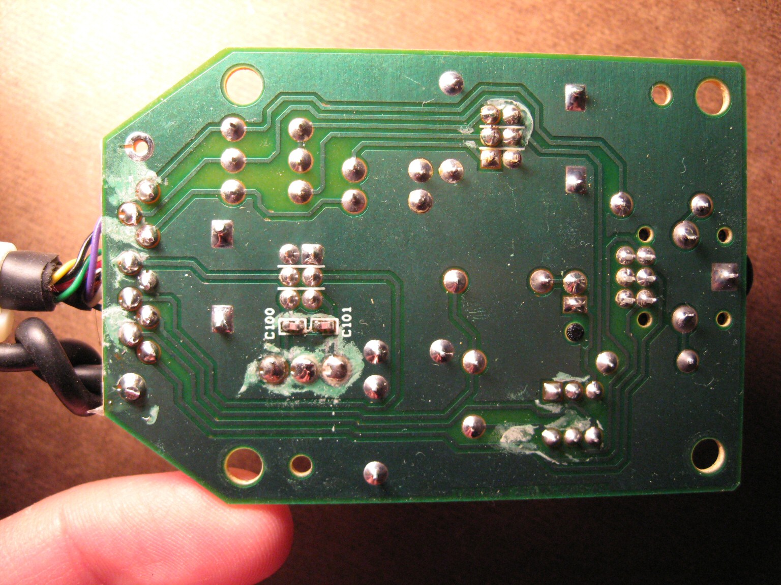
Since I cannot publicly release my replacement Z-2300 control pod PCB, or even the schematic or pinout, below are pictures taken during the disassembly of the pod:
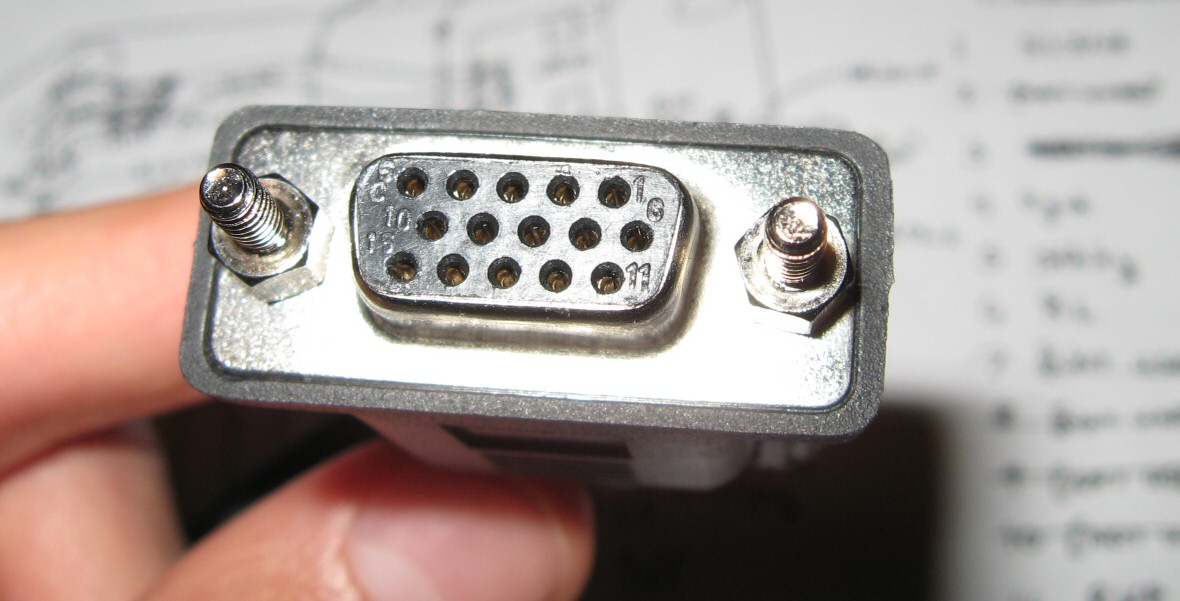
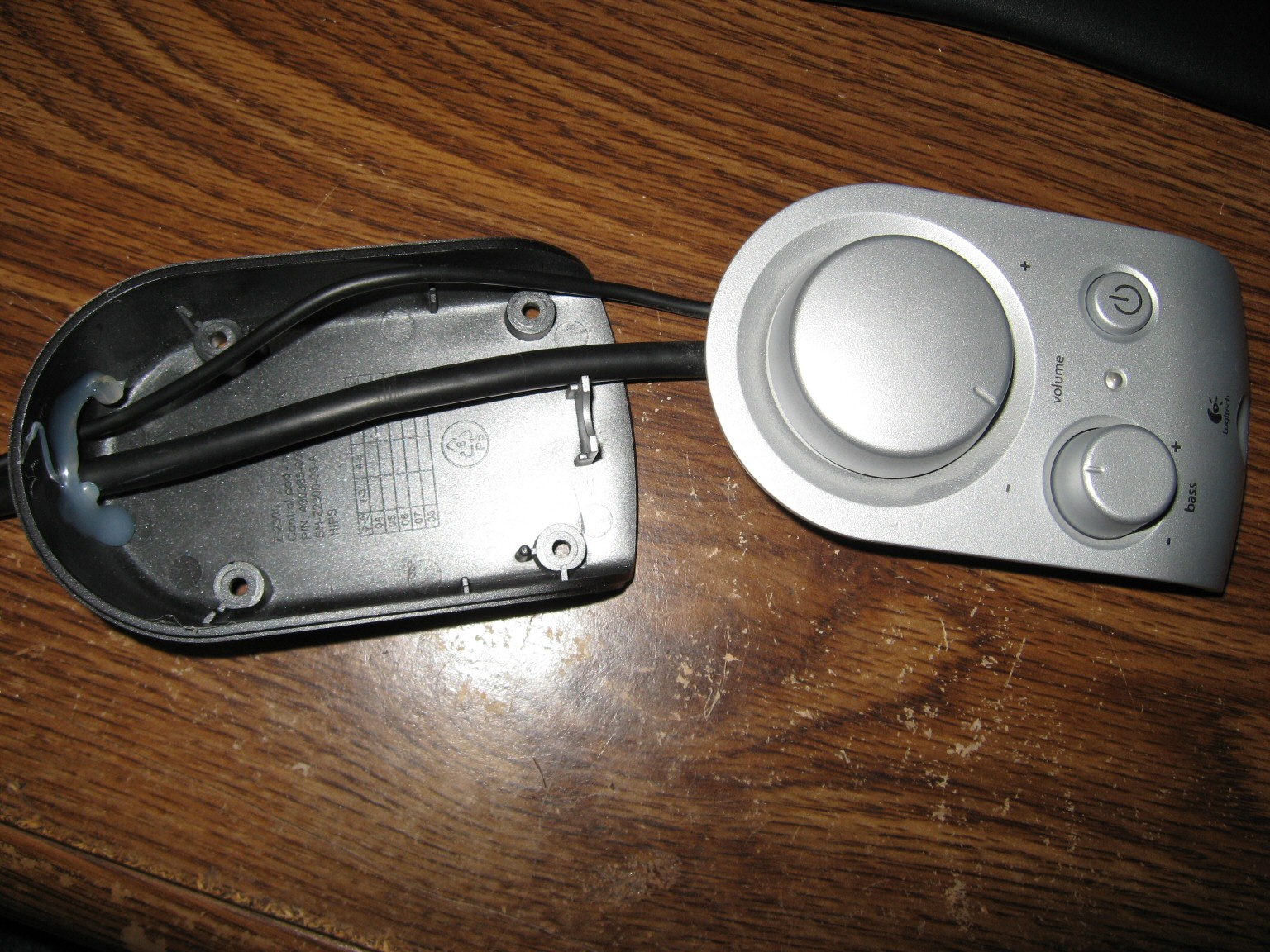
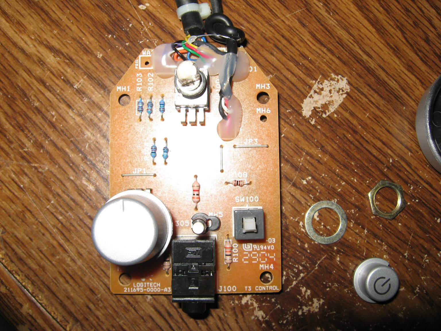

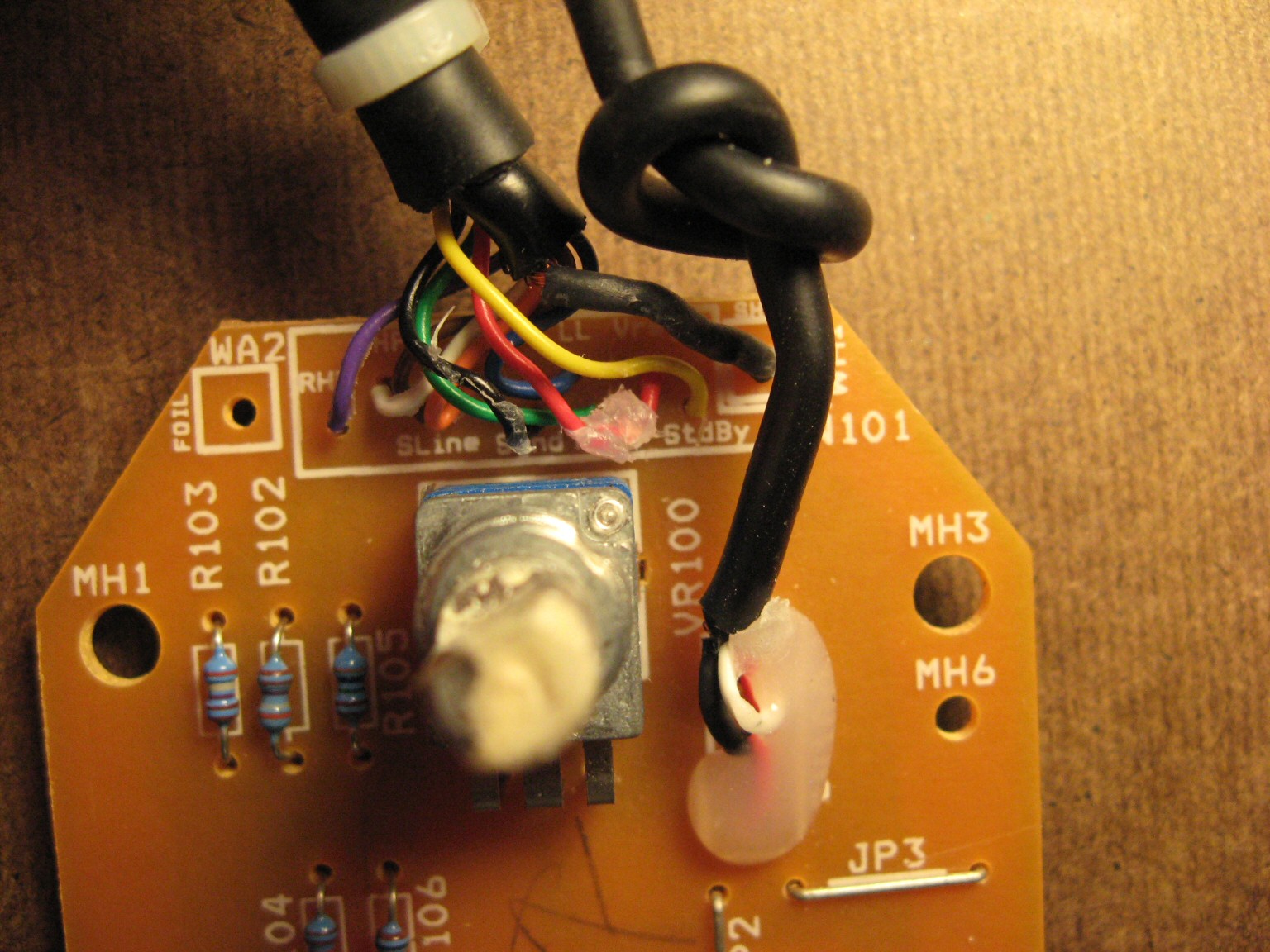
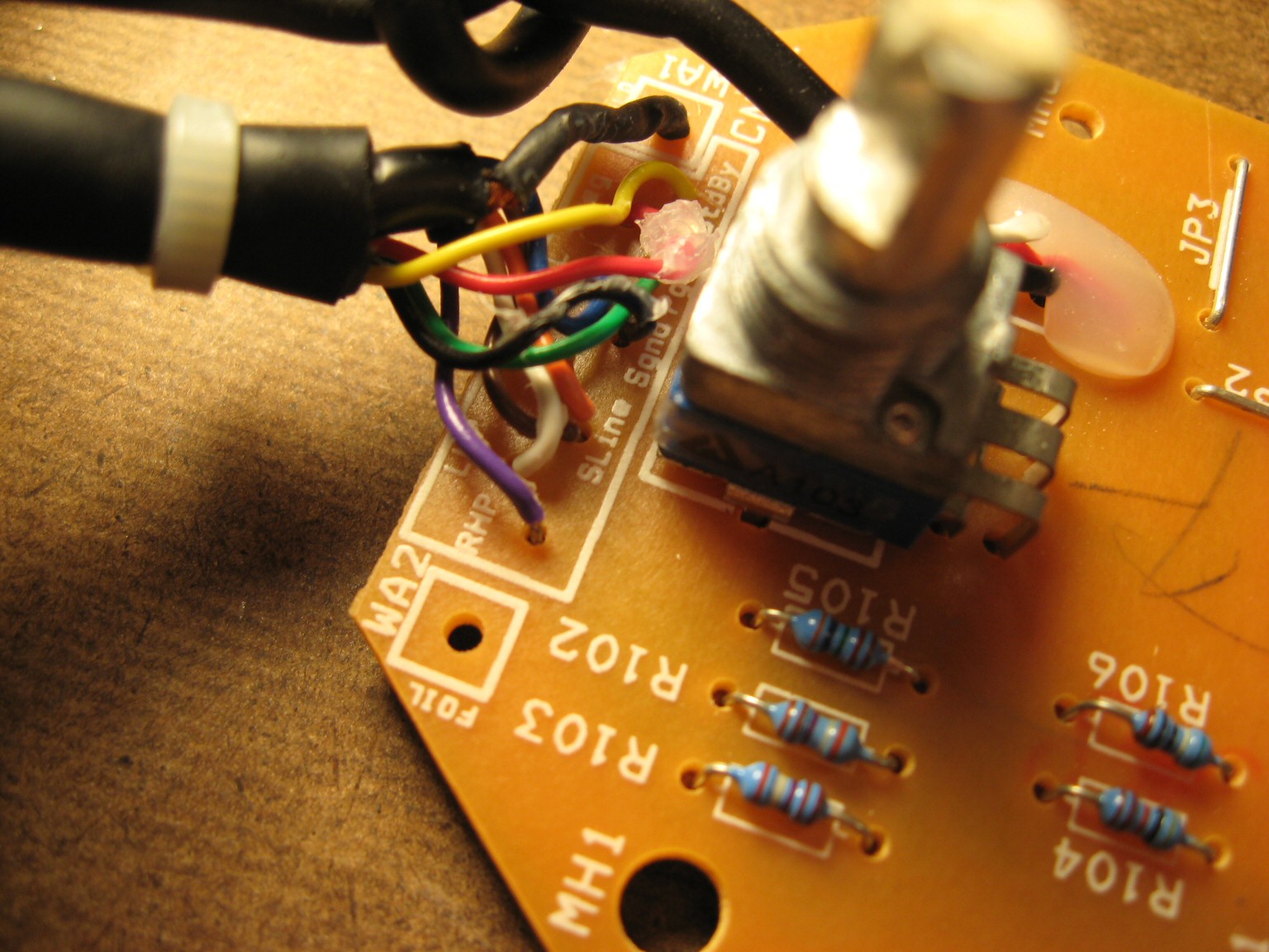
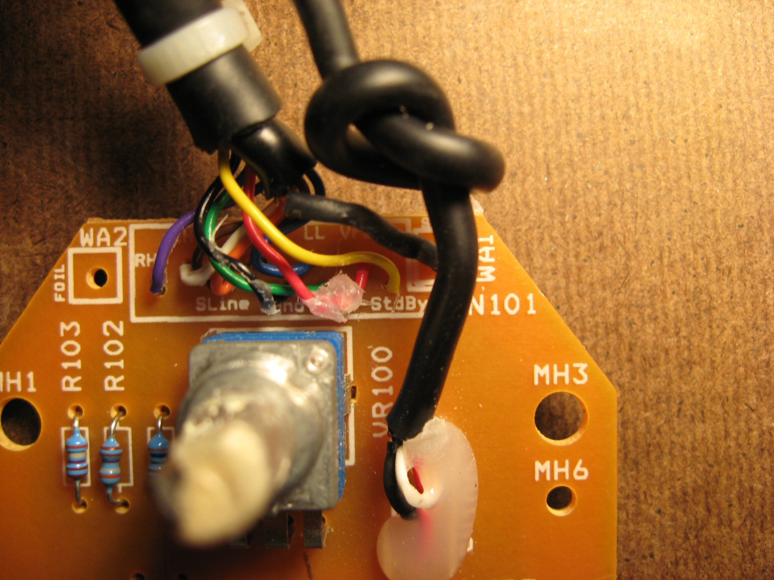
The PCB silkscreen provides wiring labels for all 9 wires (plus 1 shield “wire”). Of course, you’d have to open the pod up yourself and use a continuity checker to find out which pins of the High Density 15-pin D-Sub connector these wires go to. Lastly, I can verify Logitech’s claim that standard VGA extension cables should not be used with Z-2300’s. The center row of pins for a VGA extension cable are all tied to ground. Logitech uses a single pin in this row for an audio signal. Anyone attempting to extend the interface cable should make sure to use a pin wired 1:1 (that is, pin 1 is wired to pin 1, pin to goes to pin 2, etc., and no pins are tied together).
EDIT (April 27, 2010) – SCHEMATIC RELEASED!
DISCLAIMER: This design is for personal use only. Information is provided without warranty, either expressed or implied. Schematic and information below may contain intellectual property of Logitech.
Someone by the name of “HxCxK” independently uncovered and released a rendition of the Z-2300 schematic last month. Since he has let the cat out of the bag, below is what I originally found:

Miscellaneous schematic notes:
- Resistor R108 omitted (serves to buffer supply rail into standby pin; not critical)
- Potentiometers not measured (10k parts are common and work well in this circuit)
- Capacitors C100, C101 are optional. Someone with more free time may wish to investigate the frequency response with and without these parts.
Principles of Operation:
- A stereo audio signal comes in through the green 3.5mm connector.
- Signal passes through the remote’s main volume potentiometer for attenuation.
- Signal is then fed down to the subwoofer enclosure for pre-amplification.
- The pre-amplifier(s) distribute the audio into two places:
a) To the left and right satellite amplifier (and subsequently to the 2 speakers)
b) Back up to the remote. - Inside the remote, the signal is split again:
a) To the headphone jack
b) To the subwoofer potentiometer (where it is combined to mono at this point) - Output from the subwoofer potentiometer finally gets fed back into the enclosure and last, into the subwoofer amplifier.
D-15 Connector Pinout:
| Pin | PCB Name | Description |
| 1 | SLINE | Subwoofer Line Input |
| 2 | (unused) | |
| 3 | SGND | Signal/Audio Ground |
| 4 | PGND | Power Ground |
| 5 | STDBY | Standby, Active Low |
| 6 | RL | Right Line Input |
| 7 | (unused) | |
| 8 | (unused) | |
| 9 | (unused) | |
| 10 | (unused) | |
| 11 | RHP | Right Headphone Output |
| 12 | LL | Left Line Input |
| 13 | LHP | Left Headphone Output |
| 14 | (unused) | |
| 15 | VREG | 15V Supply Rail |
See images above for connector numbering. Those who wish to quickly test their Z-2300 can ignore most of this. The Z-2300 switches on when Pin 5 is connected to Pin 15. Then, apply audio signals as follows:
Pin 12: Left Input
Pin 6: Right Input
Pin 1: Subwoofer Input
Pin 3: Audio Ground
Printed Circuit Board:
The board can be purchased from BatchPCB in unassembled form. This is entirely non-profit. As such, NO SUPPORT IS PROVIDED. You are on your own.

Top View of Board

Top Copper Layer

Bottom Copper Layer
Parts List:
| Reference | Part Description | Part # | Qty |
| J1 | STX-3100-3C | 806-STX-3100-3C | 1 |
| J2 | STX-3100-9N | 806-STX-3100-9C | 1 |
| R102, R103 | 2.85k resistor | 271-2.87K-RC | 2 |
| R105 | 3.62k resistor | 271-3.6K-RC | 1 |
| R104 | 4k resistor | 271-4.02K-RC | 1 |
| R107 | 10.2k resistor | 271-10.2K-RC | 1 |
| R100, R101 | 33 resistor | 271-33-RC | 2 |
| R106 | 591 resistor | 271-590-RC | 1 |
| U2 | Alps RK0971221Z0 (10k, Volume) | 688-RK0971221Z05 | 1 |
| J3 | ICD15S13E6GV00LF | ICD15S13E6GV00LF | 1 |
| U3 | Alps RK09712200MC (10k, 15mm) | 688-RK09712200MC | 1 |
| LED1 | 3mm LED | 1 | |
| C100, C101 | 0.01uF Multilayer Ceramic Capacitor | C324C103K5R5TA | 2 |
| [Cable] | Male to Female, HD, 15-pin D-Sub | AE1380-ND | 1 |
i have designed an improved control pod with 2 more functions and work perfecly since 2 years .but is built in the air and not a classic and profi pcb.If anyone want to make me the gerber file i can say the improves.tnx
Hi
Would you be wiling to convert your control pod design to a gerber file?
I am willing to pay for the conversion service and access to the gerber file/ schematics.
Regards
Chris
Sorry, the files were lost at some point in the past 13 years. It should be possible to recreate from the above schematic.
Hey guys,
would anyone be able to help me with a super simple hack to get the z2300 working without buying a new remote control pod please?
For example, get an old VGA cable, join wires of pin 5 & 15 together for power to stay on;
connect pin 6 & 12 to the positive wires, and pin 3 to the common negative wire of a pair of female RCA wires, to make new audio source inputs;
install 2 pots in the MDF and connect it to which pins;
and where the resistors are supposed to go?
Any help would be much appreciated,
because unfortunately i can’t understand the schematics and PCB diagrams 🙂
Good end helpful work. Can someone give us the dimensions of PCB?
yo tengo el d-15 desmontado pero no se cules colores le corresponde a cada circuito
podrian ayudarme con eso
I absolutely love this as my control pod has died recently thank you now if i could just add in a optical dac
Yes. New developments on the now legendary and immortal Z-2300.
I tested a setup with a DSP, specifically the Thomann t-racks 4×4 mini, using the convenient quick test scheme above.
–
So, it turns out you can in fact bi-amp (tri-amp?) the thing, never mind the controller or analog volume pots. Since all three inputs are available on the Sub-D I wired up a connector, routed L&R to mono in software, put it on pin 1 with a LPF 150hz on it and L and R to pins 12 and 6. Don’t forget the 5-15 bridge for it to turn on. Results:
It works. It’s great, the sub is now independent so it can be filtered and compressed/limited, the L & R outputs can also be tailored with eq and delayed if the sub is at a distance.
The Bass amplifier has a very steep filter internally at 150hz, it can be pushed with eq to around 300hz if desired. The Highpass filters on the L & R amplifiers are cut at the same frequency. Again, very sharp filters. These can also be pushed with heavy eq to around 80hz to obtain a “fuller” sound. Logitech did this to prevent the puny desk speakers from exploding, they can’t handle anything below around 200hz. I’m using JBL Control 1 tops, those are good down to 80hz but any decent fullrange speaker would work.
The next step will be to try and locate the components on the mainboard responsible for the cutoff frequency of the HPF’s, ideally making the L&R channels fullrange by removing or adding a cap or resistor. For now, the Sub’s 150hz freq. is fine, it might benefit from being lowered to 110hz or so but I kinda like the fat sound and since I have DSP now it’s not a problem.
Note that this trick will work with any active crossover, 19″ units, car stuff. As long as it provides a separate sub signal and some form of eq or filtering it’ll do just fine.
–
CAUTION! Feeding the Z-2300 line signals directly into the sub-D without any attenuation might result in extreme noise and blown speakers, make sure to have secure connections and input signals DOWN before attempting to operate this beast.
200 Watts of Instant Deafness awaits the careless tinkerer, Ye Be Warned.
–
A big Thank You to jseaber who kept this ancient thread around for so long, providing info for anyone who happens to have or find a Logitech Z-2300. This thread is pretty much the top result if you search for a controlpod. There’s plenty of them left out there, once the control is gone they usually end up in thriftshops or ebay for next to nothing.
Most of them still work, I own and operate 10 of these bad boys and they prove to be very reliable units, even in very harsh conditions they were never intended for.
–
Dr.Z.
Anyone knows what the VREG (Pin 15) voltage ? I need a 2 Volt DC signal output and wonder if I could tap it from VREG with a DC to DC regulator so that it turns on when I turn on the remote.
Ah … Found it on the pin table above 15v.
Hello I have two Z-2300s but only one controller. I would like to use the one controller to control both subs (only one of which will drive the satellites). From what I gather all I need to do is to run wires from power, ground, signal ground, sub line signal, and standby power all in parallel from the one controller to the second sub unit. Does this sound OK? Or can I eliminate the power and power ground connections since they just run the controller (????) and already get power from the first sub?
The second sub has a broken D-Sub connector so I was going to make my own cable and bypass the connector with direct solder connections. Not relevant information to my question but just thought Id throw that in….
thanks to your post i was able to fix mine.
thank you very much!!
Hello everyone, I decided to use my Z2300 again, but I couldn’t find its pod control. So I decided to build a new one, bluetooth. Another modification will be the change from 110V to 220V.
I’m going to share this new saga of mine with all of you.
My control pod has a loud crackling problem. I know that sometimes people put a 1 uF capacitor in series with the wiper of a potentiometer to reduce bias issues. The control pod doesn’t have any such capacitor according to your circuit diagram. Do you think it would help?