Back in October I purchased a standalone Z-2300 subwoofer on eBay, knowing I could build a DIY remote control pod based on my working Z-2300 set. I disassembled my original remote and deciphered the pinout in a matter of hours. A board was sent off to BatchPCB the next day; two weeks later, I posted this video on YouTube:
Since then, I’ve received dozens of messages from fellow Z-2300 owners, all asking for more information.
Here’s the deal: It would be unethical of me to release the schematic and/or circuit board for public usage, and quite possibly a breach of Logitech’s intellectual property. There are no copyright, trademark, or patent markings on the Z-2300 speaker set or the control pod’s circuit board. However, a Logitech Product Team member at the Logitech message board writes:
“The wiring diagram is not a public document.“
This is understandable—no company publicly releases schematics for their products, and definitely does not allow for others to profit from the company’s products/services. As an engineer, I wholeheartedly respect that.
What is bothersome is Logitech’s backwards policy on replacement parts. I’ve owned my Z-2300 set since late 2005. The volume control has always exhibited terrible channel balance at low volumes. This is caused by differences in the left and right potentiometer gangs, which are pronounced at the lower and upper thresholds of rotation. Such tolerance errors are common amongst dual-ganged pots. There are two fixes: 1) Replace the potentiometer and hope for less error, or 2) Implement attenuation circuitry at the audio input (series resistors), such that the maximum counter-clockwise position of the potentiometer is avoided. I could’ve fixed this imbalance myself. Instead, it was easier to raise the volume on the pod and decrease volume at the PC. Anyway, I called Logitech’s support line one day to see about the prospect of purchasing a replacement remote control. After explaining the annoyance, I was kindly told that Logitech could send me a completely new Z-2300 set for free. Not even a shipping charge. What?! I was willing to shell out cash for a replacement part, and here they were offering to send me a $200 speaker set on their bill.
It turns out this is how Logitech’s warranty works. Rather than repair a faulty device or send out (or sell) replacement parts, they prefer to give away brand new products. I can see how the cost of labor for repairs could be less than profitable, but surely it would be cheaper to send out small replacement parts rather than entire product sets. The Z-2300’s remote control cannot be worth more than $10 in parts—probably much less considering they’re mass produced. Although fantastic for customer service, this approach to repairs is incredibly wasteful. Logitech is a fantastic company, and I was appreciative of their offer, but I declined. I did not need or want a second Z-2300 set (at the time). I was just nitpicking…
Logitech’s wasteful policy affects products besides their Z-2300. A few eBay sellers offer hand-made audio interface cables for the Z-5500, which bypass its digital remote control. These $5-$10 contraptions sell for ridiculous prices ($45-$80). Considering that there are no replacement parts to be sold, this is a clear case of demand outweighing supply. So, the question is, why on Earth doesn’t Logitech sell replacement parts? It would be profitable!
With all of that said, I would very much like to release the information I have unearthed. From the messages I’ve received, it is clear that plenty of people with out-of-warranty Z-2300’s are interested in purchasing Logitech replacement parts. Several people have lost their control pods during moves; some have dropped or otherwise broken them; some want to tap into the circuitry for unique modifications (often multiple subwoofers…); some, like me, just wanted a better performing volume control.
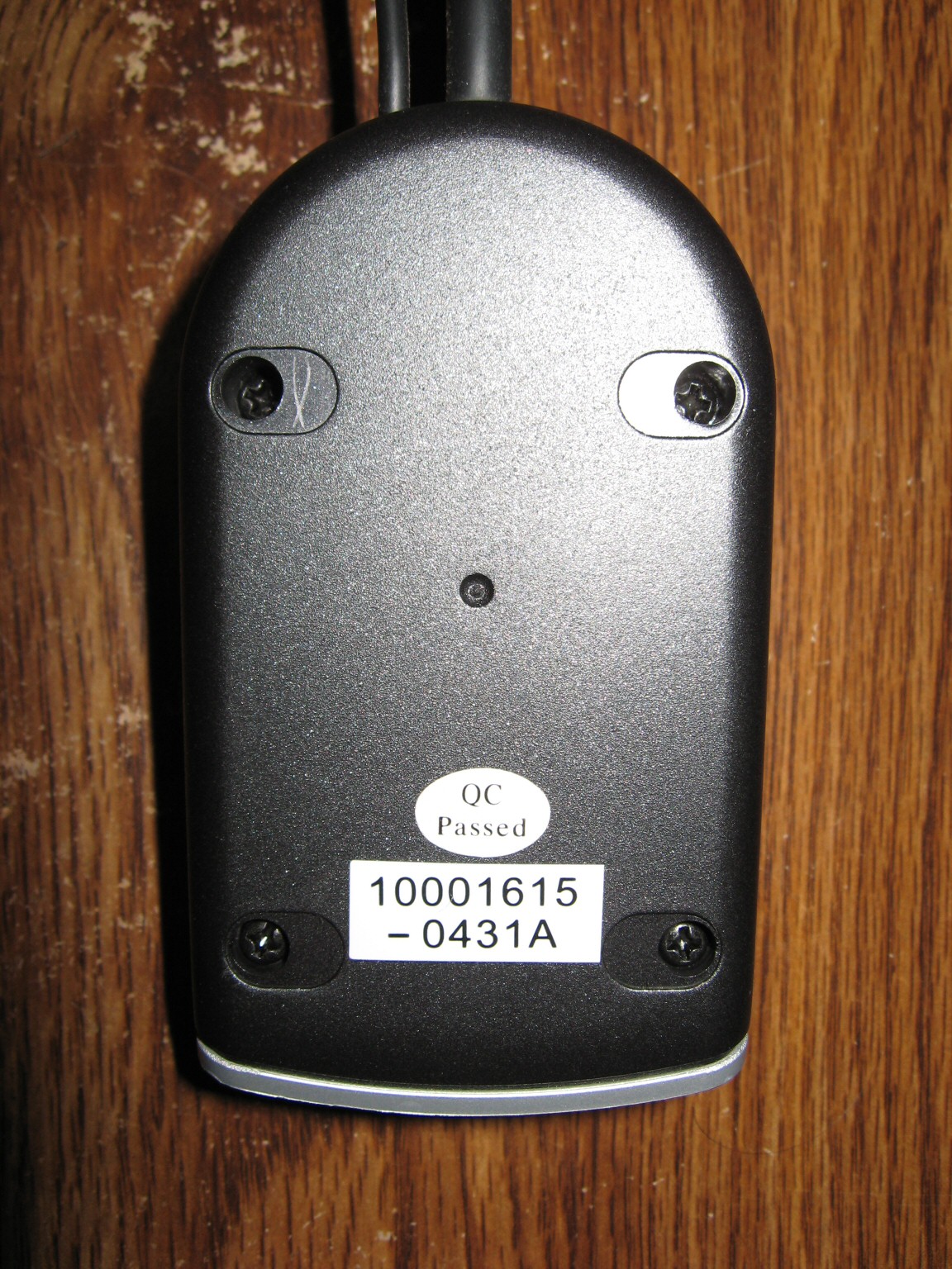
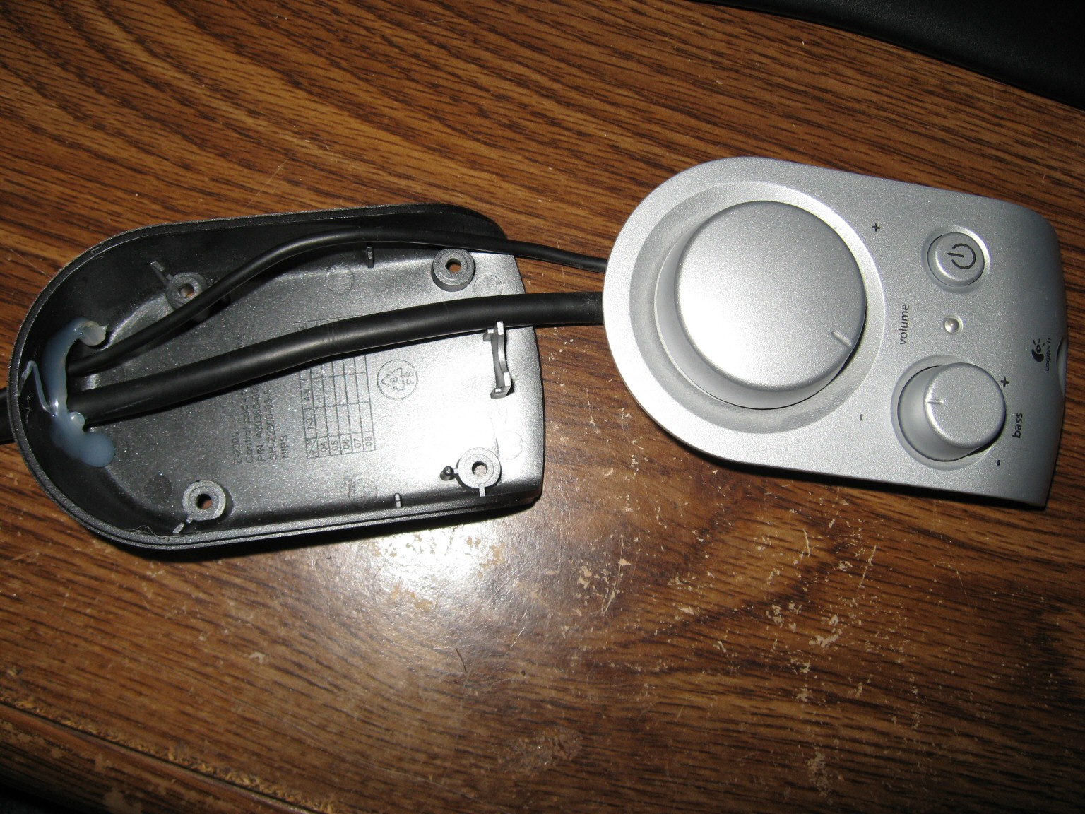
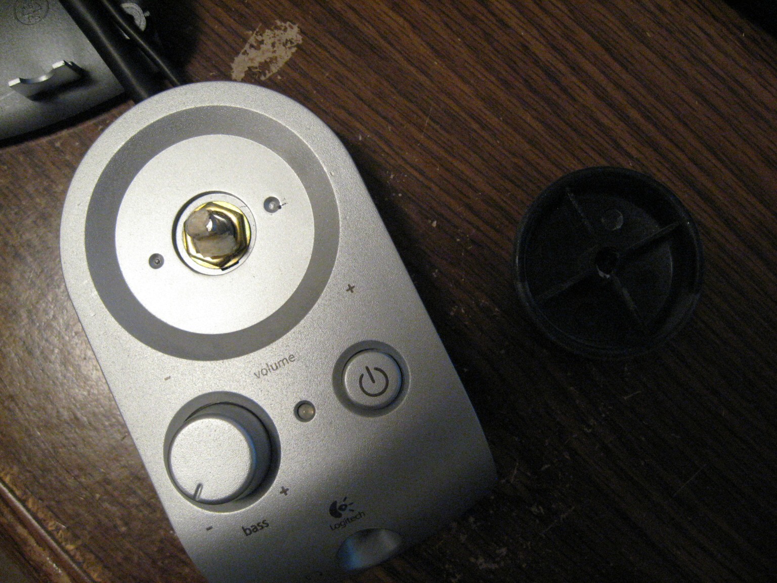
Since I cannot publicly release my replacement Z-2300 control pod PCB, or even the schematic or pinout, below are pictures taken during the disassembly of the pod:
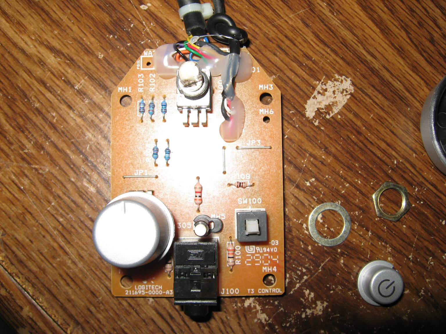

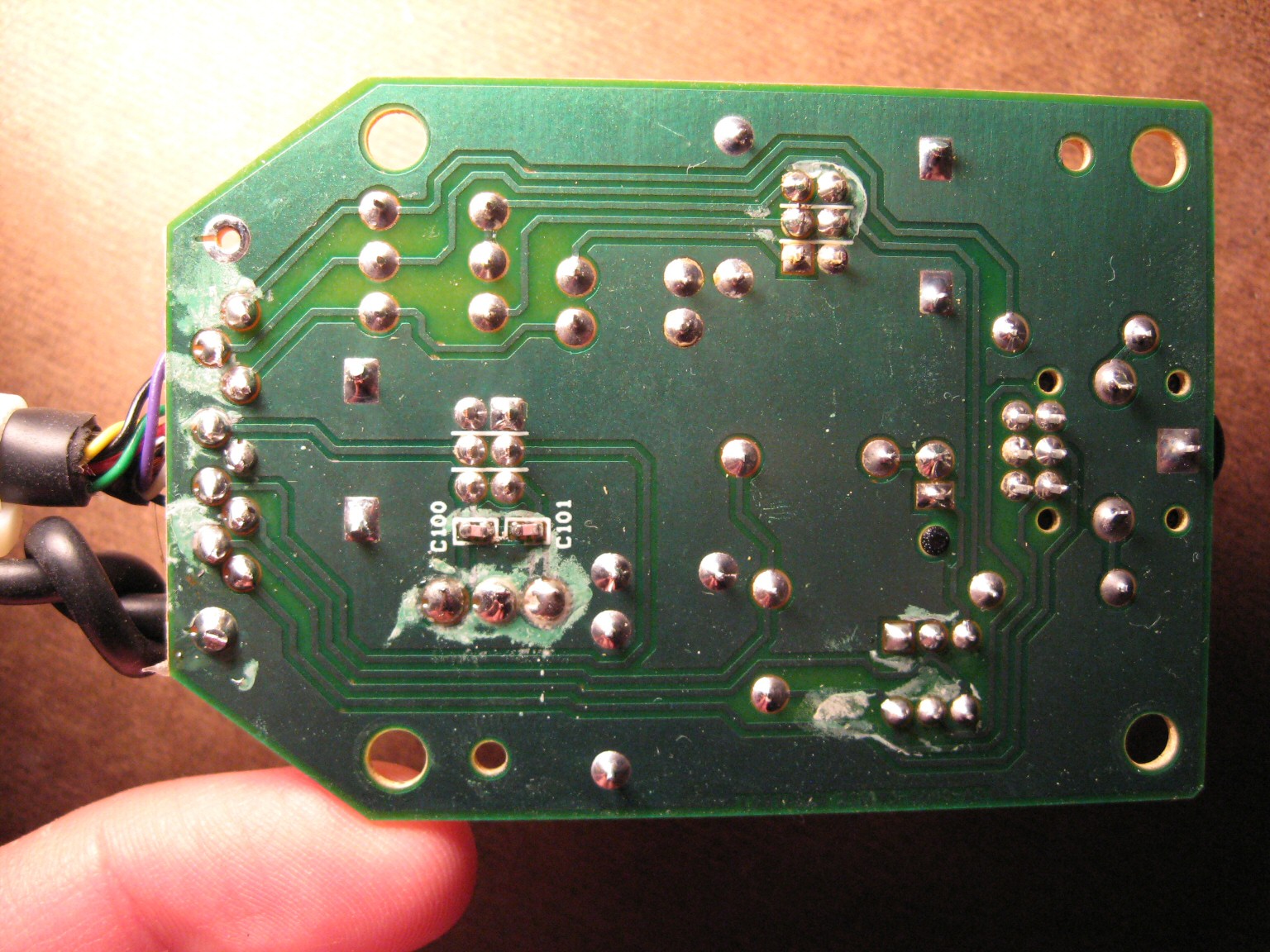
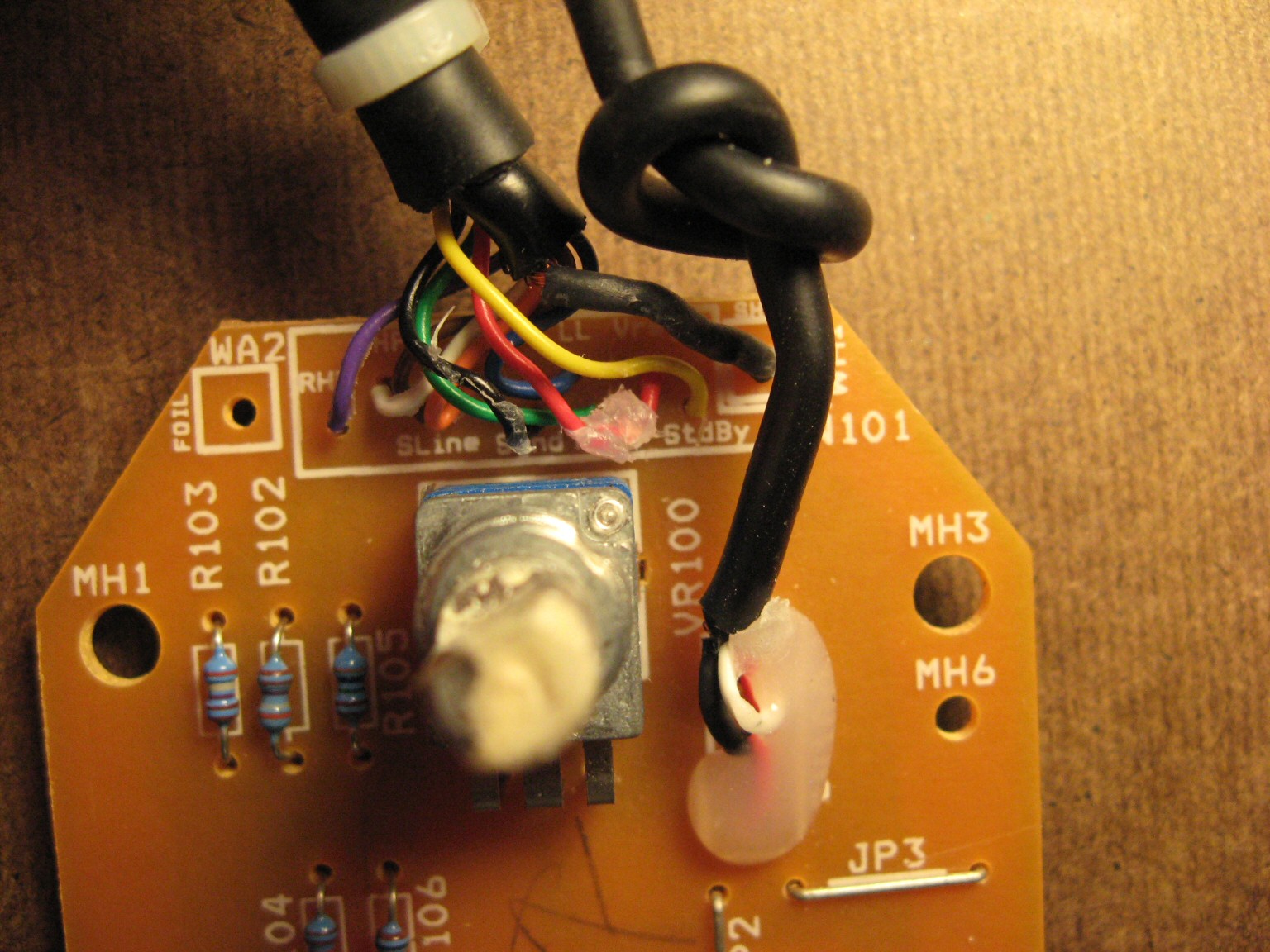
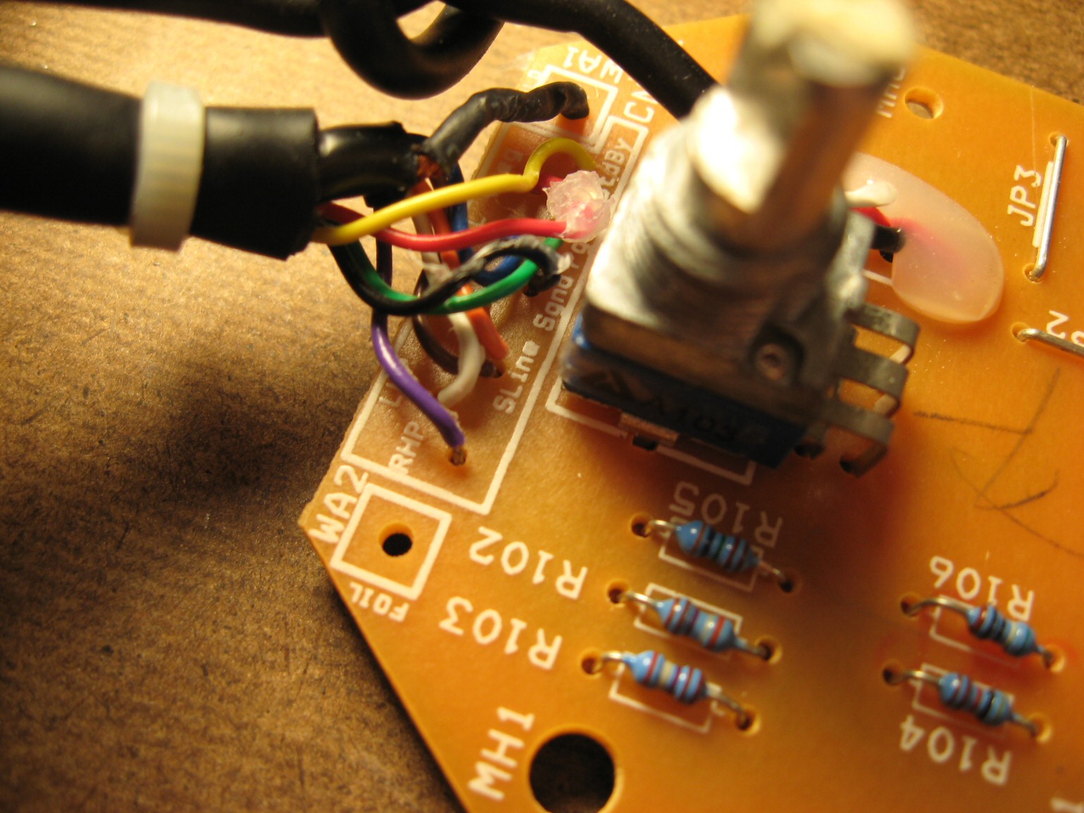
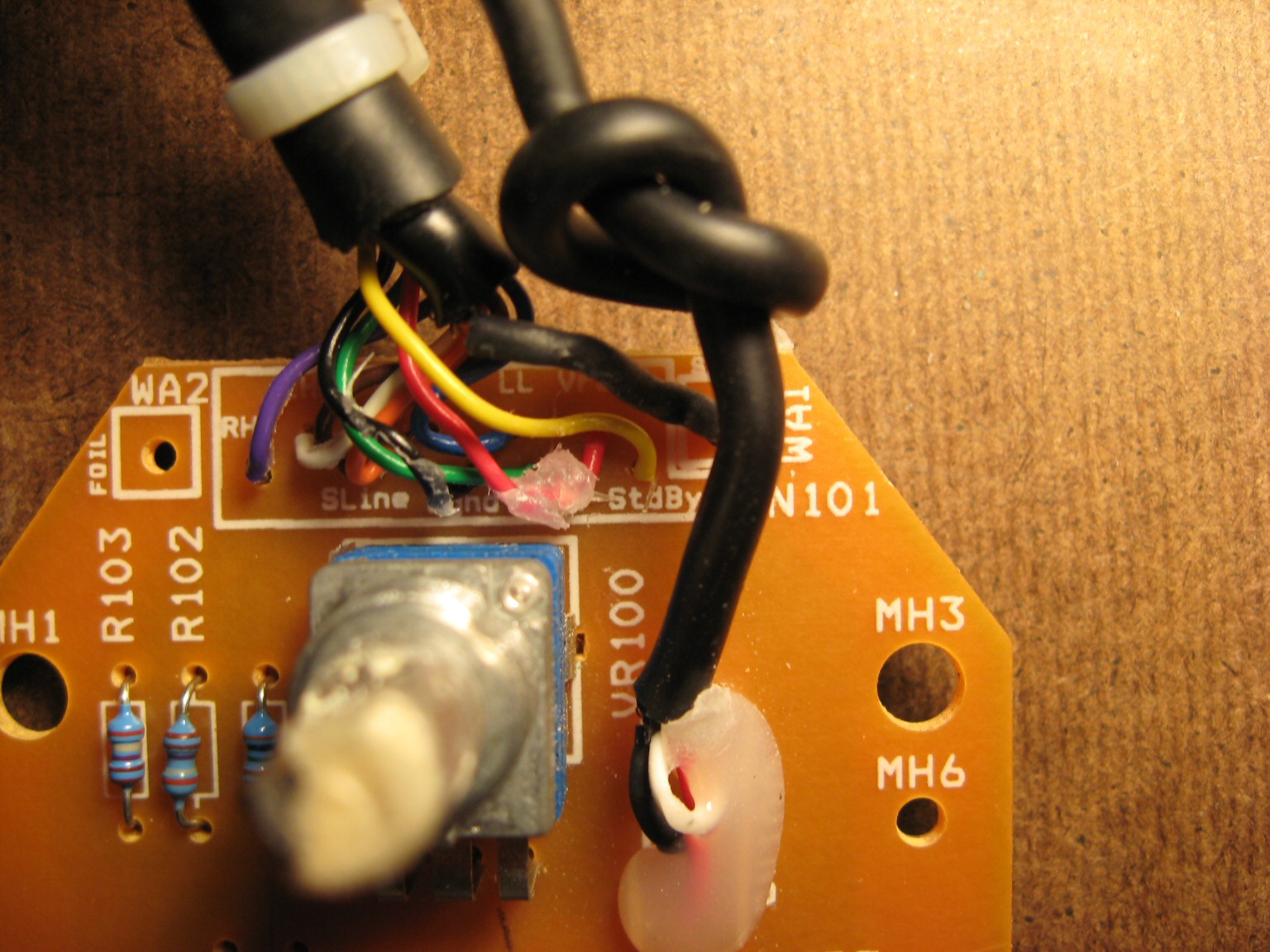
The PCB silkscreen provides wiring labels for all 9 wires (plus 1 shield “wire”). Of course, you’d have to open the pod up yourself and use a continuity checker to find out which pins of the High Density 15-pin D-Sub connector these wires go to. Lastly, I can verify Logitech’s claim that standard VGA extension cables should not be used with Z-2300’s. The center row of pins for a VGA extension cable are all tied to ground. Logitech uses a single pin in this row for an audio signal. Anyone attempting to extend the interface cable should make sure to use a pin wired 1:1 (that is, pin 1 is wired to pin 1, pin to goes to pin 2, etc., and no pins are tied together).
EDIT (April 27, 2010) – SCHEMATIC RELEASED!
DISCLAIMER: This design is for personal use only. Information is provided without warranty, either expressed or implied. Schematic and information below may contain intellectual property of Logitech.
Someone by the name of “HxCxK” independently uncovered and released a rendition of the Z-2300 schematic last month. Since he has let the cat out of the bag, below is what I originally found:

Miscellaneous schematic notes:
- Resistor R108 omitted (serves to buffer supply rail into standby pin; not critical)
- Potentiometers not measured (10k parts are common and work well in this circuit)
- Capacitors C100, C101 are optional. Someone with more free time may wish to investigate the frequency response with and without these parts.
Principles of Operation:
- A stereo audio signal comes in through the green 3.5mm connector.
- Signal passes through the remote’s main volume potentiometer for attenuation.
- Signal is then fed down to the subwoofer enclosure for pre-amplification.
- The pre-amplifier(s) distribute the audio into two places:
a) To the left and right satellite amplifier (and subsequently to the 2 speakers)
b) Back up to the remote. - Inside the remote, the signal is split again:
a) To the headphone jack
b) To the subwoofer potentiometer (where it is combined to mono at this point) - Output from the subwoofer potentiometer finally gets fed back into the enclosure and last, into the subwoofer amplifier.
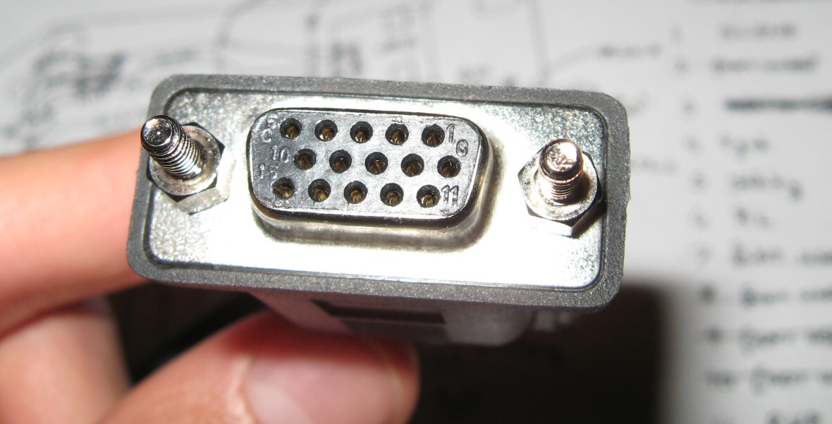
D-15 Connector Pinout:
| Pin | PCB Name | Description |
| 1 | SLINE | Subwoofer Line Input |
| 2 | (unused) | |
| 3 | SGND | Signal/Audio Ground |
| 4 | PGND | Power Ground |
| 5 | STDBY | Standby, Active Low |
| 6 | RL | Right Line Input |
| 7 | (unused) | |
| 8 | (unused) | |
| 9 | (unused) | |
| 10 | (unused) | |
| 11 | RHP | Right Headphone Output |
| 12 | LL | Left Line Input |
| 13 | LHP | Left Headphone Output |
| 14 | (unused) | |
| 15 | VREG | 15V Supply Rail |
See images above for connector numbering. Those who wish to quickly test their Z-2300 can ignore most of this. The Z-2300 switches on when Pin 5 is connected to Pin 15. Then, apply audio signals as follows:
Pin 12: Left Input
Pin 6: Right Input
Pin 1: Subwoofer Input
Pin 3: Audio Ground
Printed Circuit Board:
The board can be purchased from BatchPCB in unassembled form. This is entirely non-profit. As such, NO SUPPORT IS PROVIDED. You are on your own.

Top View of Board

Top Copper Layer

Bottom Copper Layer
Parts List:
| Reference | Part Description | Part # | Qty |
| J1 | STX-3100-3C | 806-STX-3100-3C | 1 |
| J2 | STX-3100-9N | 806-STX-3100-9C | 1 |
| R102, R103 | 2.85k resistor | 271-2.87K-RC | 2 |
| R105 | 3.62k resistor | 271-3.6K-RC | 1 |
| R104 | 4k resistor | 271-4.02K-RC | 1 |
| R107 | 10.2k resistor | 271-10.2K-RC | 1 |
| R100, R101 | 33 resistor | 271-33-RC | 2 |
| R106 | 591 resistor | 271-590-RC | 1 |
| U2 | Alps RK0971221Z0 (10k, Volume) | 688-RK0971221Z05 | 1 |
| J3 | ICD15S13E6GV00LF | ICD15S13E6GV00LF | 1 |
| U3 | Alps RK09712200MC (10k, 15mm) | 688-RK09712200MC | 1 |
| LED1 | 3mm LED | 1 | |
| C100, C101 | 0.01uF Multilayer Ceramic Capacitor | C324C103K5R5TA | 2 |
| [Cable] | Male to Female, HD, 15-pin D-Sub | AE1380-ND | 1 |
I’ve always considered the ‘Audio community’ to be an amiable one and you’ve just reinforced those sentiments. Thanks, who ever you are. I for sure won’t be able to perform the instruction set you’ve laid out to achieve my desired result but now I have something that I can take to a professional and commission him to implement the hacks.
So very grateful,
thanks again,
Bill
Thanks jseaber.
I have a problem that I first thought was coming from the Bass Unit of the Z 2300 system. I was intermittently loosing the Audio from the left speaker & the Bass Speaker… After much fiddling I have narrowed the problem down to a broken wire in the remote control unit where the cable enters the remote…. Since reading your blog I will be able to fix this problem for good…. Thanks for doing such a great job in producing your information and sharing it with others who could have problems in the future……. Regards, & thanks…. Billy
Would you perhaps be able to write a diagram on how to make a bypass cable so you can just control the sound level via your computer? I really don’t want to pay 40$ for a replacement pod or 25$ for a wire, which is a simple d sub cable.
Hi can you tell me how to bypass or the pinout of a bose companion 3 serie 1. The person that give It to me lost the control pod and i am working on how to turn It on so if you have someting that can help mi i whill apresiate It thanks you for your time
Thanks for the great info. My system stopped putting out any bass (very low volume). I borrowed another sub thinking it was my sub and the same thing. I think my remote is to blame.
Any update on where we can get the PCB? The link is dead.
Thanks again.
Did you ever find out a fix for this?
Mike
I use my Logitech z2300 for amplified TV audio. During normal video viewing
I feel the bass is too strong. I have the base control to minimum.
With all this knowledge of wiring . Could I install an additional potentiometer to Subwoofer on input wire and further limit the bass output?
in simple terms, what type and value of potentiometer do I need and how would I wire it. I would like to physically mount potentiometer on subwoofer. Plan on drilling hole on back panel to mount pot. Would I interrupt the wire on pin 1 with potentiometer?
Thanks for sharing that with us!
I bought a Z-2300 without remote for 35€ (~40$) and with your shematic I made a Remote for 15€ (~17$)
Here a pic, the quality of the pic is not the best.
Thanks, great job man!
[img]http://abload.de/img/2015030804194223ut9.jpg[/img]
Hello, I recently bought a z2300 off ebay.It appears to be in really good condition. Control pod works good no noticeable problems with volume pot. I have it connected to my TV. My problem is the bass is overpowering even with the bass to minimum. I installed a simple toggle switch in the sub box to turn off the subwoofer when family is around. How can I get more adjustment out of the bass control on the pod? Would a 10k pot in series with that #1 wire for the sub input give me more adjustability? I wonder if these replacement pods on ebay go from no bass to max bass similar to a regular amplifier Thanks
Hi,
How complicated is it to create one of these things? I have zero knowledge with soldering. Any ideas for me?
Help…. please lol
My Z-2300 control Pod failed and not being remotely handy at this stuff I purchased a cable type remedy on ebay. http://www.ebay.ie/itm/251839594290?ssPageName=STRK:MEWNX:IT&_trksid=p3984.m1497.l2648. It is a cable with a vga type connector on one end and a 3.5 mm connector on the other. My issue is, even though my speakers are working again the sound is completely different. Any ideas why this might be.
The builder probably used a potentiometer which differs from the original component value. This part seems to have a noticeable effect.
Thanks for that info(and the very prompt reply). The sound from the speakers is also much, much louder. Even with the audio playback software(Creative Mediasource 5 Player) set at 45% and the speakers(Win 7 playback device) set also at 45% it begins to sound like the speakers might blow if I upped the volume much more. I think I may be better off buying one of the actual control pods available to purchase on ebay, at least those devices have a vol control handy and they are more likely to behave similar to the original control pod.
Cheers,
Gerry.
Hello, I was wondering if anyone knows, or is willing to investigate, and explain findings about this cables values.. I am probably unable to afford the resources to learn about so much, partly having seemingly much less comparative, and related knowledge, to easily come back with a greater contribution myself, at this time.
I have concerns about the employment of this cable regarding noise and coloration.
I understand that the oem system adds a bass boost to the satellites(at least) via an affect in control pod handling, in all circumstances, but can be escaped by user modifications to the pod.. I understand this is done to drive the satellites harder, and perhaps the sub as well, since mid-range via the satellite 63.5mm(?)(2.5in) driver, is lacking, compensation is made to support the systems frequency range. This might explain why users who’ve employed a third party control pod; find a different bass response. 2(a)(b) Without the stock control pod affect on the signal.
I had imagined that any lower mid range boosting might be avoided by using this cable. Reading this post here, however, I am left with even more questions regarding the signal handling. And I do not have the original system, or equipment, in it’s entirety, for a personal ab comparison, nor the tools for objective testing. I am also time broke due to personal matters.
I intend to use this system, hopefully without the satellite bass boost effect, in conjunction with a speaker array(is that my new term? I think so).. where multiple speakers, and amps, handle a signal, and more cone is employed in the mids, and upper bass. So the inherent systems boosting for compensation is less desirable by me at this time. Anyhow, more information here about the bypass cable system is of interest, and there is demand. Thank you for making this resource available.
but this leaves me with even more questions since I previously understood signal modifications happened in the control pod, i figured doing away with it would do away with the system-specific affected signal, for myself, however, after reading your comments, i cant help but wonder, what is happening to the signal in the sub box. Is it all being boosted, or just the bass response or just the mids?
Perhaps bass boost is happening all in the control pod, and this polarized affect is being amplified to a certain degree, which is meant to account only part ways for the satellite deficiencies, and then after the signal is split, again boosts the whole signal.. to account for the remainder. So what may be happening, by employing this cable, is resulting in us getting a whole signal overdrive, instead of a stock frequency range boost?
To address your question, I think in “normal circumstances”, the speakers should only be able to draw what they are capable of handling, however, we do not have a “normal” circumstance here, since the signal is intentionally affected.. and these speakers might be designed specifically to handle the affected signal as it is.
I would hazard a guess that your speakers should not blow up.. though I suspect they are working out of design parameters. Maybe a signal equalizer would help? Does only the volume in the bass or mid region seem increased for you Gerry, or are the higher frequencies and lower, also affected by this volume boosting?
Secondly, to determine the problem, to the benefit of other interested parties, while employing this cable; can you match the volume coming from the subwoofer; to the volume of the stock control pod? With the satellites unplugged, coloration of the situation can be avoided. Say using a test sound. If we had a meter, we could capture the volume differences, and make the setting to the pods, or cable. To see if we can match them for at least a certain sound. Find a good reference point for the stock z-2300 speaker system, maybe 50 percent volume, and 50 percent bass? Whatever produce the most “normal” volume.
Switch to the new cable or control pod. Having a bias in our adjustment towards less bass dial and more volume attenuation, and make adjustments towards an even point. Maybe we could find better test results, matching a low bass sound, first, and then try to match to a higher bass sound. leaving the software as it is throughout all tests. Or start at a high frequency..
In fact, first you might find, with the satellites plugged in, does affecting the bypass subwoofer nob have ANY affect on the volume of a bird sound? Crank’er down then, crank’er up for the test! Return the bass nob to it’s position prior, this bird frequency test.
After this, match the two control pods as close as possible, leave the knobs where they are throughout the following procedure. Plug in the satallites, and run a test sound, at a high frequency, like a bird sound, use a metre, or your ear, mark a value of one control. Taking a few samples is often good practice and in many cases could produce a more consistent result and more accurate finding. Switch to the stock control pod, and take a sample using the same sound, do the volume measurements match each other? Roughly? OR, is the volume offset the same difference as found in the lower bass region?
This can help indicate to us if it is just a difference in a local affected range, say the mid range or if the high frequencies and low frequencies are also adjusted.
Now, understanding this result, and having marked down some values, maybe notch the control knobs, and give them percentage values. Then we can test the frequency range around the satellites lower bass region and find the difference. And take lower mid range samples now. First from the sub, without the satellites, then the satellites. Take a few samples up the frequency range.. They say the z-2300 satellites kick in around 120-150hz mark.
Now, I would like to know , without the satellites, can you perfectly match the sub response, volume and sounds, across it’s frequency range with the control pod, and with the bypass cable? And if not, which sounds better? Or more accurate?
With all this data we can graph our findings, and see the problem, and possibly account for it ourselves, here and now. Or help us or others have a better understanding of what is involved, with using this cable, bypassing the stock control pod, using other third party solutions. This information, otherwise not here, legwork, and findings can be of benefit likely to many others than just ourselves.
FYI, in the event that I do not return, you might be able to download an equalizer software for your computer system.. or use a y-splitter, 3.5mm to rca, to reach physical equalizer hardware, before mating the source to the speaker system. This would let you attenuate individual frequency ranges. This might help overcome a problem in the case where the frequencies are abnormally affected by boosting, either in a certain area, or across the board, but especially if the problem is local to a certain range, or broad and linear. Stereo equalizer hardware can be had on the cheap, just for this purpose, I suppose, on ebay. I have one I got for free when moving into a residence once upon a time..
PS. Glad posting here doesn’t require membership.
Also Jseaber, your article hyperlinks to the pcb solution offered beforem are no longer available.
2a
http://www.amazon.com/gp/customer-reviews/RSITDBJM7NZB9/ref=cm_cr_pr_rvw_ttl?ie=UTF8&ASIN=B00KTT5N4U
2b
http://www.amazon.com/gp/customer-reviews/R11F66CSHBIZYO/ref=cm_cr_pr_rvw_ttl?ie=UTF8&ASIN=B00KTT5N4U
Not a diy guy at all. Thanks for showing the hidden screws. LOL
Hey, I’ve been having a problem with sound coming out of my left channel and was wondering if you could help me diagnose and fix the problem.
When I switch the speakers, the sound switches to the other speaker. When I unplug the speaker in the right channel and turn the volume up very high, I can hear sound coming out of the speaker plugged into the left channel. When I plug my headphones into the headphone jack, sound only goes to the right ear, but plugging headphones directly to the computer works out fine.
Is the problem in the control pod or the subwoofer, and how do I determine the area of the bad connection?
Please help me or guide me to the proper resources. I am quite desperate.
Please help! I have the same problem. I thought purchasing this control pod would solve the issue but it didn’t. I now am receiving sound in both speakers but not the subwoofer.
http://www.ebay.ca/itm/Logitech-Z-2300-Computer-Speakers-Control-Pod-New-Black-Version-Replacement-2300-/221179235421?pt=LH_DefaultDomain_0&hash=item337f4f4c5d
Hi there,
it seams to be a problem with amp in subwoofer. To be specific – with the part called ‘Power output stage’ for a left channel. It’s a chip soldered into PCB. You have to go to electronic workshop to fix that.
Hello, i have a small question about your Logitech Z2300 diagram. I see you said that you can omit capacitors C100 and C101, if i do that, does it mean i also mustn’t connect sound ground that goes from capacitor to ground?
hola amigos alguien tiene los planos de el z5300. no tengo el control y quiero dejarlo con el volumen directo, se puede?
Does anyone know the name of or have a link to Batch PCB? I went there looking for the board but I have no idea how to search for it & with 1200 + pages of boards……..
Hello Jseaber,
I am trying to fix my Logitech G51 control pod. I am trying to determine the pin-out. It also works with a d15 connector to the subwoofer. Can you explain me the steps i need to take to do the pinnout. The wires are named in codes from wa1 to wa22. Some wa codes are left out. the total amount of wires from the d15 connector are 15 so all wires are used.
Greetings
Matthijs W
Those who wish to quickly test their Z-2300 can ignore most of this. The Z-2300 switches on when Pin 5 is connected to Pin 15. Then, apply audio signals as follows:
Pin 12: Left Input
Pin 6: Right Input
Pin 1: Subwoofer Input
Pin 3: Audio Ground
************************************
My question is, how would i control the volume of the sub if i were to follow the above? or would the output volume be at max by default if the above is followed?
the colors of the cables are.
Hello you experts!
Hopefully someone can give me some advice on my z-2300 problem that just popped up this past week. The right channel will not turn down all the way. At mid-volumes, both speakers are at approximately the same volume, but as I turn down the volume knob, they both go down in volume together to a point, after which the left continues down to zero, but the right stays at the same volume (which is much too high when I’m coding, reading , or on the phone at work).
I was hoping the cause was accidental changes to my PC sound settings, but connecting it to an iPod showed the same results. I’ve found a temporary work-around by setting my PC volume really low, so that I need to turn up the Logitech system higher to compensate, which puts it in the range where it works properly. However, reducing the PC volume so much decreases fidelity, so I would really like to fix the Logitech problem.
I am not as familiar with electronics as most on this thread, but I am willing to give a repair a go if it is within reason of a hack like me! Has anyone had this same problem or at least knowledgeable about the cause?
Thanks for any advice you can give.
-Don
Hi guys… my z2300 control pod headphones output its with a malfunction that makes the pod mute the speakers like it has always a headphone plugged 🙁 there´s a way that I can bypass this? I dont matter lost the output for the headphones… but I want my speakers output back!!!
i just got me a z-2300 woofer. i have three things missing. both left and right speakers and the volume control.
on hand i do have different speakers rated as the original so i am really looking for the control pod.
if anyone wants to help a guy with this project, please email me a price that is other than the prices i am finding online. i understand supply and demand and i read logitect will not sell replacement parts. that is so stupid to begin with.
if you cannot support the item you are selling than you are providing a disservice to anyone that buys one.
i do have this woofer, and it is missing those a & b speakers and control pod.
i found one seller of the speaker’s would not go lower than 50.00 each which = 100.00 + shipping and 44.00 for the control pod. at these rates it seams it is better to de-stress and just buy a new outfit.
after reading about all the fuss about parts, is this device really worth all this energy? is it just better to scrap the whole thing and just buy from someone else. there must be a 2.1 out there that sounds just as good. any advice on a brand that sounds just as good that i can look into? email me and i thank you in advance. with all the problems this item seams to generate maybe if logitect does not care, you all should show the same and treat it like junk-greg
You can replace the Left and Right speakers with any ordinary bookshelf speakers. Simply wire the +/- terminals to an RCA connector. You can likely find used speakers on Craigslist.
As for the control pod, you’re correct that it’s hardly worth replacing. DIY is the best way to minimize cost.
Image 1
Image 2
this is how I did my fix. in one of the photos there are diodes to make this system Stereo, but it didnt work for me so I just made Mono system. also I neglected to add potentiometer on sub input. numbers on some pins show which pin is numbered which from the list this guy listed above. it works for me. spent 3 hours salvaging components from somewhere to use in my z2300 and it works perfectly. NOTICE: some tight packed soldering skills are required for this fix. feel free to do this if you want to spend $0.00 on wired remote 🙂
Hi,
My right speaker doesn’t work. The speaker itself is fine since when I plug into the left out, it’s working. I would appreciate it if you let me know how to fix it.
Have a great day
Thanks,
Bob
Hello I followed your blog about the control pod for z2300 speakers and I just happened to have a problem with my set so I check everything out since I wasn’t getting sound and found a short in the audio input cable and what I did was replaced the cable with a new one that I soldered onto the board and now works just as new total cost 1.99 to replace the cable.
Good post, now this information should be available for a very long time, likely much longer than you own this domain 🙂
http://web.archive.org/web/20160620081539/https://blog.jseaber.com/2010/02/27/logitech-z-2300-control-pod-disassembly/
Using this info I was able to revive a near-dead Z-2300. The amp now powers 3 subwoofers (1×12″, 2×6″) @ 7ohms total. Also powers (2xMids and 2xTweeters) @ 12ohms on Left and Right channels. The sound is very nice despite running 11 speakers in total from this underrated amp. It pulls over 350Watts from the wall.
My buddy also uses the original Z-2300 satellites and sub in his car and it sounds like a professional car-audio system.
I’m interested in saving my Logitech z-560 speaker system, (great speakers!) but have no electronics building experience to build my own control pod. The control pod for the z560 differs from the z2300, but suffers the same design faults. I see replacement control pods for both z560 and z2300 speaker units on Amazon sold by SummitLink for $40. The z560 and z2300 control pods by SummitLink appear to be identical, with the only difference being the subwoofer cable connector. These control pods seem like a great alternative, but the SummitLink z560 control pod has complaints of the knobs being “too sensitive”. I’m not familiar with electronics and am unable to build my own. Is purchasing the SummitLink $40 control pod my only option to or is there a cheaper and better alternative?
The DIY schematics posted here are for the z2300 and like I said, I have no electronics experience, so it’s all foreign to me and I wouldn’t know where to begin building my own.
Thanks!
Z560:
https://www.amazon.com/dp/B00TJHU67W/ref=cm_sw_r_cp_api_MFMXxbJ7PHN2P
Z2300:
https://www.amazon.com/dp/B00KTT5N4U/ref=cm_sw_r_cp_api_KMMXxb2J4KSG6
So is the bass level on the control pod a simple bass boost or is it an actual subwoofer gain control? I currently have two powered presonus studio monitors as my mains, but I’m using the z2300 and control pod without the mid/high speakers attached, only as a subwoofer. It works great this way.
anyone has a complete circuit diagram of a Z2300?
My plan is to convert this beauty to a compact bassguitar amplifier
Hi,
The batchpcb site seems to have moved to oshpark, a similar service!?
Anyway, the links not working, can’t order the board.
Can you provide the file or a working link?
Thanks!
How can I get you a cup of coffee? PayPal?
Hello, I’m trying to repair my z2300 and am having trouble identifying a particular component on the amp PCB. The label on the board is D102. I’m fairly sure it’s a Zener Diode but am looking for confirmation/specifications. I have very little understanding of how these circuits work but can usually get the job done if I have good circuit diagram from which to work. Any help is greatly appreciated.
Here’s an image of the board. It’s at the bottom center of image. Just below the blue capacitor. [img]https://goo.gl/images/nehD1z[/img]
Sorry bad link above
[img]http://www.electro-tech-online.com/imgcache/10811-39e61b363b.jpg[/img]
Hi all I know this an old thread but hoping somebody knows the answer.
I want to replace the phone connector on my Z-2300 Control Pod.
Can anybody help me out finding out the replacement part.
After reading the comments and the post I saw this one not sure if that would be a direct replacement.
http://www.mouser.com/Search/ProductDetail.aspx?qs=sGAEpiMZZMukzO2buB5fm6wPUOsDHO88gp0mFGE0CKI%3d
Thank you.
Hello Jseaber:
Thanks for your knowledge page and effort !
And would you please kindly tell me how to do with the black cable on the position on WA1? thanks ![img]https://image.pushauction.com/0/0/2412f193-cea9-4fd1-8ea0-20c79d59b9f9/62e0ee18-2870-44eb-85bc-a3326b9bd02b.png[/img]
Thanks for all the info! My control pod started having issues recently after years and years of use. Fortunately my problem was a short in the audio input line. Rather than replace the line I installed an auxiliary input port. It’s working great!
I’m sure others have already done this but I hadn’t seen any yet.
[img]https://drive.google.com/file/d/1twfNoy6CJFYjEqnwvNB6FZN8h6pUhR57/view?usp=drivesdk[/img]
[img]https://drive.google.com/file/d/1twfNoy6CJFYjEqnwvNB6FZN8h6pUhR57/view?usp=drivesdk[/img]
Image link broke, trying again
Alps RK0971221Z0 (10k, Volume) http://www.mouser.com/Search/ProductDetail.aspx?qs=Xb8IjHhkxj6R%252bVLTJlRoZA%3d%3d
and
Alps RK09712200MC (10k, 15mm) http://www.mouser.com/ProductDetail/ALPS/RK09712200MC/?qs=fQ8kcZGzY5Wzud3OJDlECg%3d%3d
looks different than this on board. Why?
Mouser often uses a single stock photo for an entire line of parts. Pictures will not always match reality.
Hey,
My plan is to add a remote power switch whilst still using the original controller.
This would allow me to use a small 5v relay, powered by the USB port on my amp so when the amp is off so is the power on the sub.
I thought about just using STDBY and VREG directly, but R108 will take a shed load of current. I wonder if it would be as simple as removing R108 and adding a switch between STDBY and VREG as I originally thought?
Any idea what the best way would be? The switch that’s in there just now has 6 pins so that’s no use for my single throw single pole relay. Any thoughts appreciated!
Thanks again for your reverse engineering.
Oh and plan B is just to use the relay to switch the mains input to the unit but would prefer a low voltage alternitive 🙂
Hi Nathan – Interesting idea. Sorry, it’s been years since I tinkered with this circuit. Briefly revisting the schematic, I imagine you could drive a low current relay coil from a USB port, with the contact (switch) replacing `POT_SW` in the Z-2300 pod. Or even better, wire the contact inline with `POT_SW`. You’ll have to get creative lifting the potentiometer switch pin(s). Totally possible.
What I ended up doing was plan B – using a 5V relay across the main switch in the rear of the unit directly. This has the advantage of completely cutting power so no quiescent current at all. Now when my AV reciever is off the sub is completely off. Result! It’s handy having multiple USB ports in the reciever so not compromising anything else.
The problem I have is the sub woofer stopped working, I believe I found the problem in the fact that the potentiometer that controls the base was reading as an open circuit so I have attempted to replace it.. My first attempt at soldering and electronics so learning fast… but damaged the copper connectors taking out the old one. I have attempted to reconnect it back up as per where it connects and seems to align with schematic. However I have no idea where the second gang of potentiometer pins connect to and I still have no base (sub woofer).
Please help
https://drive.google.com/file/d/1kkOiZNwzi9v4lZd2Tj25LMCQjtNINoyEfg/view?usp=sharing
Even a way to test if the sub woofer is working by bypassing the remote would be useful
I picked up the sub only at a thrift store hoping that I could hook it up to my 5.1 stereo receiver. Is there a way to get an LFE (single RCA) input into this system without having to procure a remote?
Thanks
By that, I mean, can I cut two of the four leads from the RCA input from the circuit board and solder that (An LFE input) into the subwoofer inputs to the sub amp and get it to work? Which wires to which pins (on the primary PCB pin out).
Hey Scott, did you get this to work?
hola jseaber , mira tengo una sola duda porque hay 2 capas de cobre una superior y otra inferior y una cada una tiene algunas pistas como diferente algo asi
hello jseaber, look I have one doubt because there are 2 layers of copper one upper and one lower and one each has some clues as different something like that
I hope you help me
For whom it may concern,
Please note that the resistors in the bass control section are all 1% resistors and their values are absolutely critical, in particular R106 which sets the level of bass signal fed back to the main unit. It MUST be 590 ohm, substituting for a higher or lower value E12 resistor will mess with the balance between high and low output.
I suspect logitech did this to make it even harder to go out and make your own control pod.
SO, to make an accurate controlpod which sounds exactly like the original one, use 1% resistors as follows:
R102/R103 = 2K87 1% metalfilm
R104 = 4K02 1% metalfilm
R105 = 3K65 1% metalfilm
R106 = 590 ohm 1% metalfilm
–
These are all E96 series precision resistors which might be a pain to procure. They are however the exact same values logitech used.
The rest of it isn’t critical, the series led resistor is for a blue led, you might want to use a higher value for red/green ones.
–
In my z-2300’s, I have 4 of them, i modified the bassunit so the 2 pots are next to the 15 pin connector. I drilled 2 holes for the pots, wired them directly to the corresponding pins on the 15 pin conn. and converted the rca outputs to inputs so you can plug in a simple rca cable. Be sure to apply generous amounts of glue/gunk to avoid hissing through its holes. There’s a lot of pressure inside the enclosure when really playing loud.
The speaker outputs in my units are now Speakon terminals mounted in the mdf enclosure next to the amp baseplate.
The modification is not that hard, although the pots are a pain to fit between the pcb and the rca terminal. Also you will need a steady hand to solder the wires directly to the 15 pins on the main pcb.
The big advantage of this mod is that you will never have to fiddle with a control pod again, my z-2300’s are basically mini-PA systems, using any medium power 8 ohm speakers found at thriftshops. I prefer JBl control 1’s by the way, they sound excellent on a Z-2300 sub and can handle the power easily.
Happy Hacking,
DrZ.
Interesting idea moving vol pots but you still use the control pod to feed and power the sub?
No, control pods are not necessary anymore.
I used normal, storebought potmeters since I always buy z-2300 without the controlpod. They are dirt cheap if the control is missing or dead.
When modifying them, I simply wire the pod’s components, only a few resistors, between the pcb inside the z-2300 and the potmeters. As described, i turn the two rca sockets from speaker outputs into line-inputs, they are conveniently placed near the vga socket and when you drill two holes for the pots between the rca’s and the vga you can wire it all up with simple cat5 wires. When you open a z-2300’s backplate you’ll see how that works. There’s just enough space between the edge of the pcb and the rca sockets to put two potmeters in.
Do you have images of how you have the resistors lined up?
I just recently picked up the z-2300 woofer box for $10 at a Goodwill and with the variations that everyone has contributed, I’m at a loss of even where to start.
The only thing similar to this that I’ve got experience with was an Acoustimass Module woofer which was easy, all I had to do was find the LR channels through the serial port and
then just plug it into the sub RCA port on the stereo receiver. This is a headache at best and the more I read it, the more confused I become, when looking at the board references and then trying to makes sense of it from there.
Hi Doctor X, thanks for your post on the forum. I have the z2300 sub and would also like to use it in the same way you have: convert the RCA outputs into inputs, install 2 speaker outputs in the MDF enclosure and mount 2 pots (one for satellite speaker volume, one for subwoofer volume) also in the MDF. Please can you send me photos, or diagrams to assist, unfortunately im not smart enough to decipher the PCB diagrams?
i understand how the positive input RCA wires inside go to pin 6 &12 of the VGA terminal, and the negative wires join and go to pin 3. Join pin 5 and 15 with a wire for power to be on. And connect the original output wires that used to go to RCAs for satellite speakers, to the new output terminals im planning to install. But i do not understand what pins to connect to the pots, and where the resistor are supposed to go.
Hi,
Thanks very much for this but where can I buy the PCB? I do not see it on the batchpcb website.
Regards
Hi everyone,
I would just like to let everyone know my findings after fixing my own original control pod for my z2300.
The reason everyone has issues with the control pod is due to the left speaker no longer working. This is actually due to the line in cable failing and nothing else. Over time the core of the cable breaks therefore causing signal loss.
I have today fixed my control pod by replacing the line in cable using a 3.5mm jack to 3 core bare end cable. The cable is one meter long and has the required third core for the ground/control signal. It can be bought off eBay for less than £2.
Hope this helps anyone who has this issue but can’t build a replacement controller or doesn’t want to buy one. You just need a soldering iron in order to unsolder the old cable and solder the new one in.
Hi
Very good write up, I have a question about some other make of PC speakers I hope it is ok to ask?
Do you have any idea if a headphone socket could be wired to Harmon Kardon HK395 2:1 PC speakers. If it can be done how would I go about doing this?
Thank you
I ordered a new vol control from Mouser RK09L12D0A1W, awesome service btw, Texas to Toronto in 1 day. New control plus re-flowing the board connections fixed my problem.
I did try building one with local supplier parts based on schematic but wasn’t successful.
HI
Thanks for this wonderful post. Much, much more informative than others.
I just wonder what the purpose of the R106 – 591 Ohm in parallel with the subwoofer input?
Does this act as a low-pass filter?
If I am building a quick-and-dirty circuit for sub-only input, do I need it?
Tim
The 590 ohm resistor is only an attenuator, it provides a pretty low resistance for the return signal to the sub and forms a voltage divider with r105. The reason for this is the fact that they use the high-power headphone signals coming from the z-2300’s internals to sum the left-right components and attenuate the mono bass returnsignal. The resulting signal without the r106-r105 divider would be way to high for the bass amplifier section’s inputs.
The filtering for the bass and high signals is all done in the z-2300’s preamp section with active filters, the pod is just a passive device for convenience but it does make the design a bit unlogical.
Hey guys,
Kinda reviving this as its a pretty cool project and i plan to succeed. i happened to get the Z-2300 for free from someone who wanted to throw it off. I was fortunate enough to find this thread and got it to work but i have a slight issue. The left channel from Pin 12 doesnt seem to work for some reason. I also purchased a bypass cable (in which the sub doesnt sound as good because it doesnt have the filtering resistors i guess). With that cable the left channel and right channel works well. Im wondering, is this happening because i dont have the complete circuit wired up? i have everything wired up except the headphone out from LHP and RHP. I also have the exact value resistors because previously, i used E12 resistors which matched up to the required values. so i was hoping that getting the exact value resistors will solve the weird issue with the left channel not recieving anything. Ive tested with multiple jacks as well.
Another strange discovery is that if i use pin 14 (which is unused) instead of 12, left and right is detected but left is heavily attenuated.
Hi my friend Logitech z623 can not find the vga connection of my device is broken? I don’t know which colored tip will be connected to how many VGAs they don’t want to do. Do you know anything about it thanks
Hola.buenos días tengo la duda si logro resolver el problema con la salida izquierda.
Y cuál fue la solución,por que yo tengo el mismo problema.
Si me pudiera ayudar lo agradecería muncho. Gracias
Verifica si el TDA7294 de ese canal esta dando un voltage offset
The Z-2300 is the best computer speaker ever built,,,after some equalization nothing sounds like it,,,I am speaker builder I know what I’m telling
Not only is it a computer speaker.
I use z-2300’s in pairs for mobile dj soundsystems. For small gigs 2 units, for bigger ones 4. Instead of the stock topspeakers I use JBL Control 1’s which can handle serious amounts of power and will survive playing max volume for several days(!)
While they might not be the absolutely loudest PA system, they sure do sound a whole lot better then comparable sized PA systems.
A while ago I hosted an area at a dancefestival where all other area’s used Funktion One speakersystems but quite a lot of people noticed our area as being more warm, rich sounding, more relaxing for the ears even when it was shockingly loud. THX-Certified clubbing, who would have thought? This was an area of approx. 200 people, next time I’ll bring four z-2300’s and put them at the four corners of the area for better coverage. This time I only had 2, which says a lot about the power of the z-2300.
It is a near-perfect small speaker system for any occasion where you want banging loud sound that sounds absolutely faithfull and well balanced.
These units deserve nothing but high praise.
Hey Doc. you seem like the man i need to talk to. I have 6 Z 2300 amps. Im making a min PA system. I plan to get 6 more and go up to 12 subs. There in mini Scoop enclosers.
What my problem is, is can i control the sub volume and satalites seperatly? For example could i turn the satalites down and the subs up as i play Dub music and want the bass higher than the mids. I have worked out that the satalites get the main volume and pass it back to the subs. Want to be able to turn the satalites down without turning down the bass signal. I was thinking to use a small preamp and volume pot to conect a signal to pin 1 then use a un preamped signal to the regular input. Does this make sense?
Hello fellow rebuilders!
Just got my hands on a Logitech Z-2300 without the control pod and the satelites for free.
My plan is to rebuild it as a active subwoofer for mye workshop.
I followed the schematic just as it says (I am a computerengineer and very used to soldering but just do not understand audio.)
It works, BUT max volume is probably 4% if the max volume with a real control pod. I can bearly hear it. But the potentiometer do adjust the volume from 0 – 4%, so do the subwoofer potentiometer.
What can i be doing wrong? The funny thing is that when i remove signal ground (pin 3 on the 15pin) everything gets reeeeeal loud, but when i then pause the music, there is a constant low noise coming from the woofer. probably at 50% of max volume.
Can any1 help me out here? I can provide both video and pictures of my setup.
Thanks in advance!
Are you sure you used the correct pot? There are linear and logarithmic ones, maybe you used the wrong variant?
Hello
Does anyone have greber files? I can’t draw a pcb to make a board. I have this set without a remote control and would like to use it in the bedroom.
Hi all,
two extremely left hands here but the controlpad is exactly what I need!
Does anyone know any other way to get it, except for the manual option?
Thanks in advance!
Hi , can I get a link to buy the pcb please ? I don’t find it on oshpark , my z-2300 remote start to have problems, my right speaker doesn’t have much sound anymore, I even replace de 3.5 Jack cable . Since the control pod is hard to find anymore or to expensive I I’ll like to give a try to build one on my one . I kindly ask you please someone help me to buy this pcb , I really don’t want to give up on my z2300 !!
esti din romania?
Da