Back in October I purchased a standalone Z-2300 subwoofer on eBay, knowing I could build a DIY remote control pod based on my working Z-2300 set. I disassembled my original remote and deciphered the pinout in a matter of hours. A board was sent off to BatchPCB the next day; two weeks later, I posted this video on YouTube:
Since then, I’ve received dozens of messages from fellow Z-2300 owners, all asking for more information.
Here’s the deal: It would be unethical of me to release the schematic and/or circuit board for public usage, and quite possibly a breach of Logitech’s intellectual property. There are no copyright, trademark, or patent markings on the Z-2300 speaker set or the control pod’s circuit board. However, a Logitech Product Team member at the Logitech message board writes:
“The wiring diagram is not a public document.“
This is understandable—no company publicly releases schematics for their products, and definitely does not allow for others to profit from the company’s products/services. As an engineer, I wholeheartedly respect that.
What is bothersome is Logitech’s backwards policy on replacement parts. I’ve owned my Z-2300 set since late 2005. The volume control has always exhibited terrible channel balance at low volumes. This is caused by differences in the left and right potentiometer gangs, which are pronounced at the lower and upper thresholds of rotation. Such tolerance errors are common amongst dual-ganged pots. There are two fixes: 1) Replace the potentiometer and hope for less error, or 2) Implement attenuation circuitry at the audio input (series resistors), such that the maximum counter-clockwise position of the potentiometer is avoided. I could’ve fixed this imbalance myself. Instead, it was easier to raise the volume on the pod and decrease volume at the PC. Anyway, I called Logitech’s support line one day to see about the prospect of purchasing a replacement remote control. After explaining the annoyance, I was kindly told that Logitech could send me a completely new Z-2300 set for free. Not even a shipping charge. What?! I was willing to shell out cash for a replacement part, and here they were offering to send me a $200 speaker set on their bill.
It turns out this is how Logitech’s warranty works. Rather than repair a faulty device or send out (or sell) replacement parts, they prefer to give away brand new products. I can see how the cost of labor for repairs could be less than profitable, but surely it would be cheaper to send out small replacement parts rather than entire product sets. The Z-2300’s remote control cannot be worth more than $10 in parts—probably much less considering they’re mass produced. Although fantastic for customer service, this approach to repairs is incredibly wasteful. Logitech is a fantastic company, and I was appreciative of their offer, but I declined. I did not need or want a second Z-2300 set (at the time). I was just nitpicking…
Logitech’s wasteful policy affects products besides their Z-2300. A few eBay sellers offer hand-made audio interface cables for the Z-5500, which bypass its digital remote control. These $5-$10 contraptions sell for ridiculous prices ($45-$80). Considering that there are no replacement parts to be sold, this is a clear case of demand outweighing supply. So, the question is, why on Earth doesn’t Logitech sell replacement parts? It would be profitable!
With all of that said, I would very much like to release the information I have unearthed. From the messages I’ve received, it is clear that plenty of people with out-of-warranty Z-2300’s are interested in purchasing Logitech replacement parts. Several people have lost their control pods during moves; some have dropped or otherwise broken them; some want to tap into the circuitry for unique modifications (often multiple subwoofers…); some, like me, just wanted a better performing volume control.
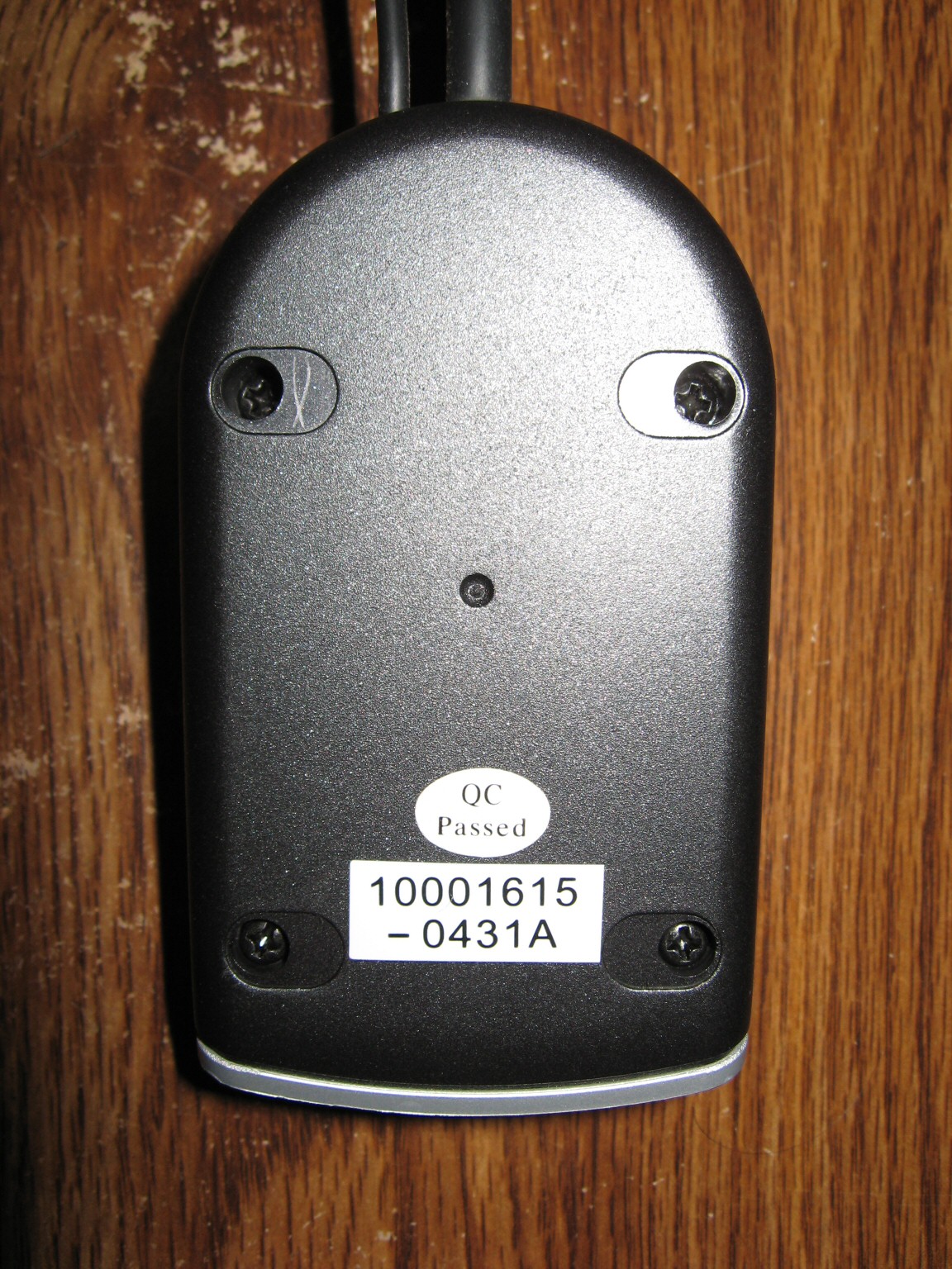
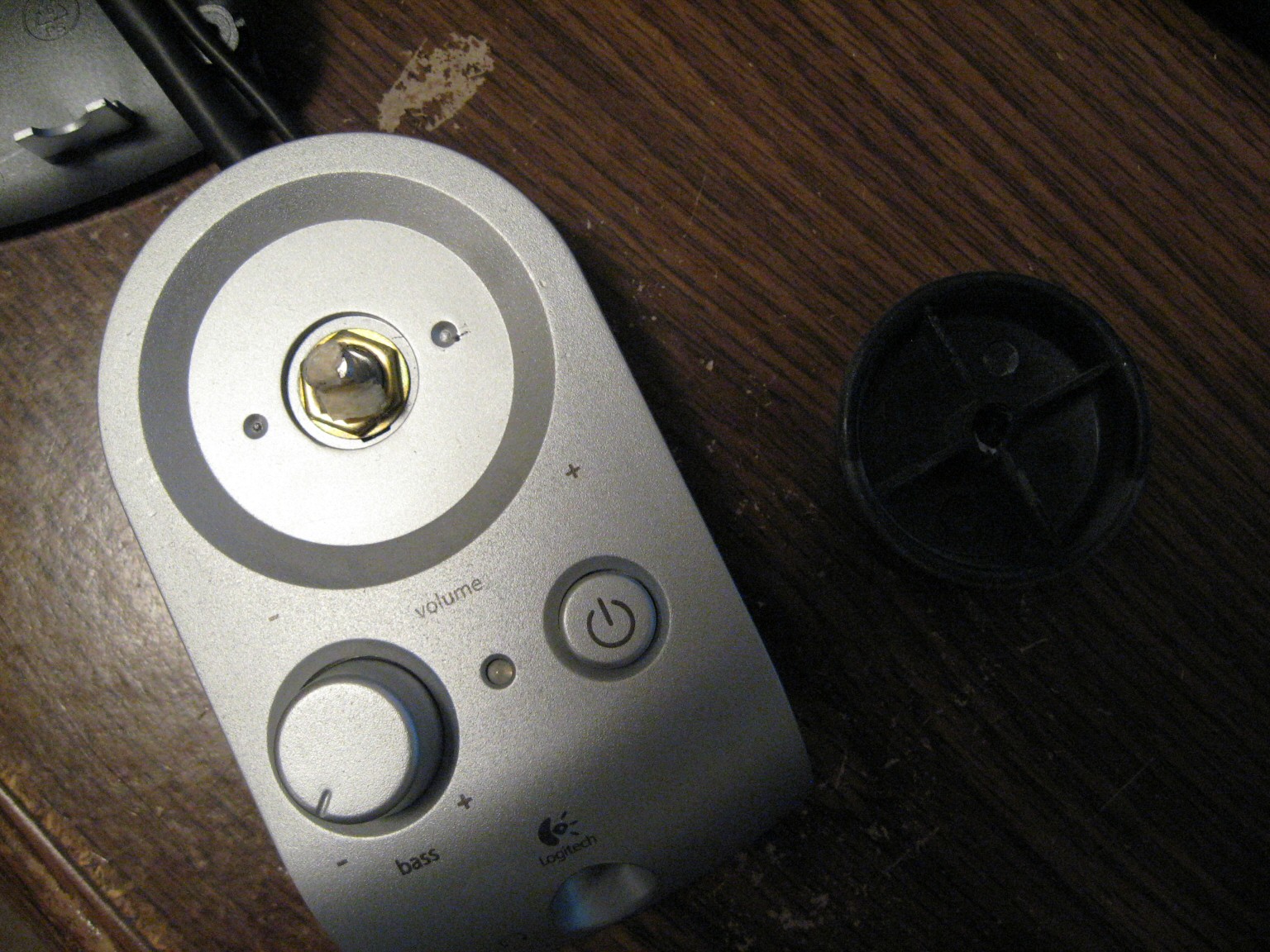
Since I cannot publicly release my replacement Z-2300 control pod PCB, or even the schematic or pinout, below are pictures taken during the disassembly of the pod:
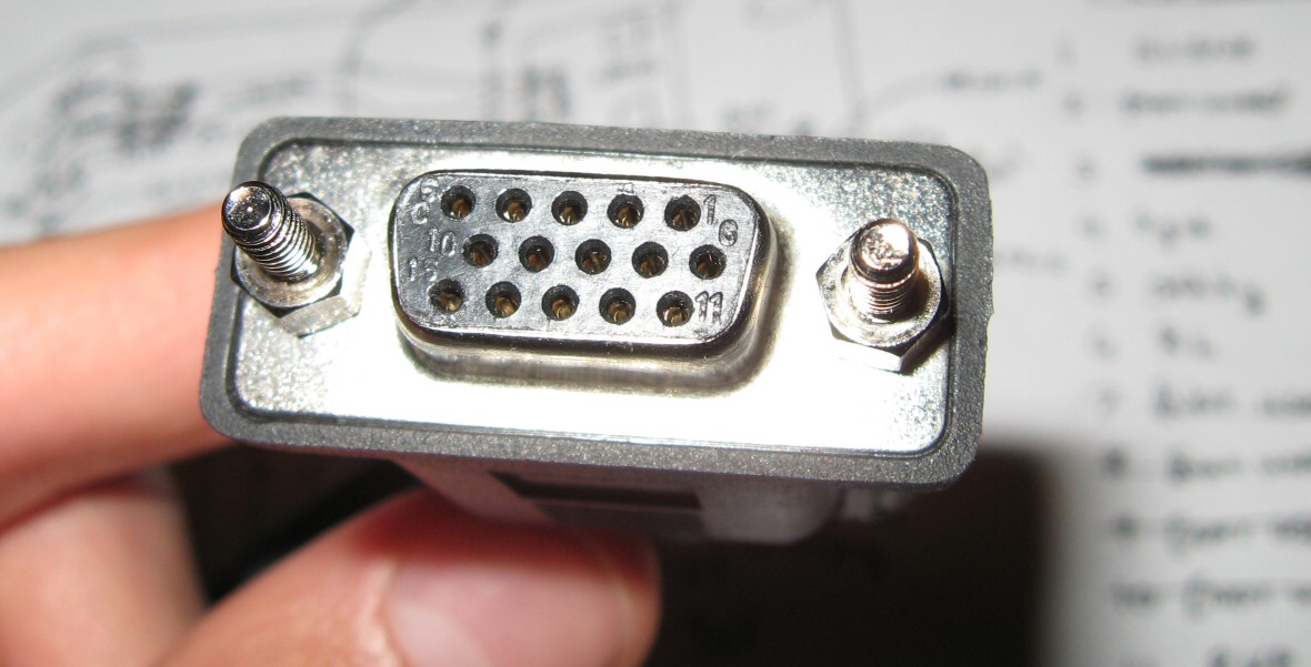
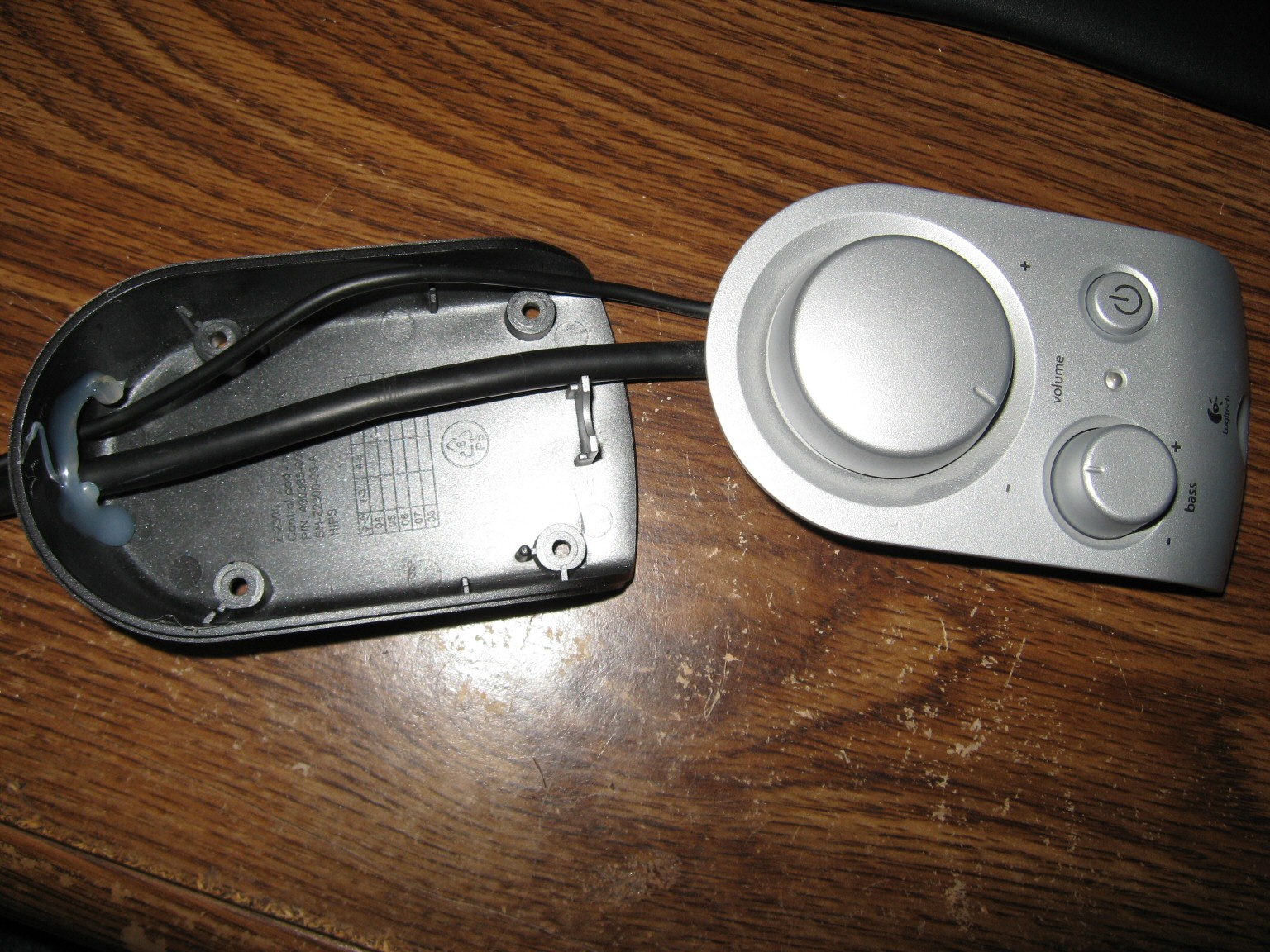
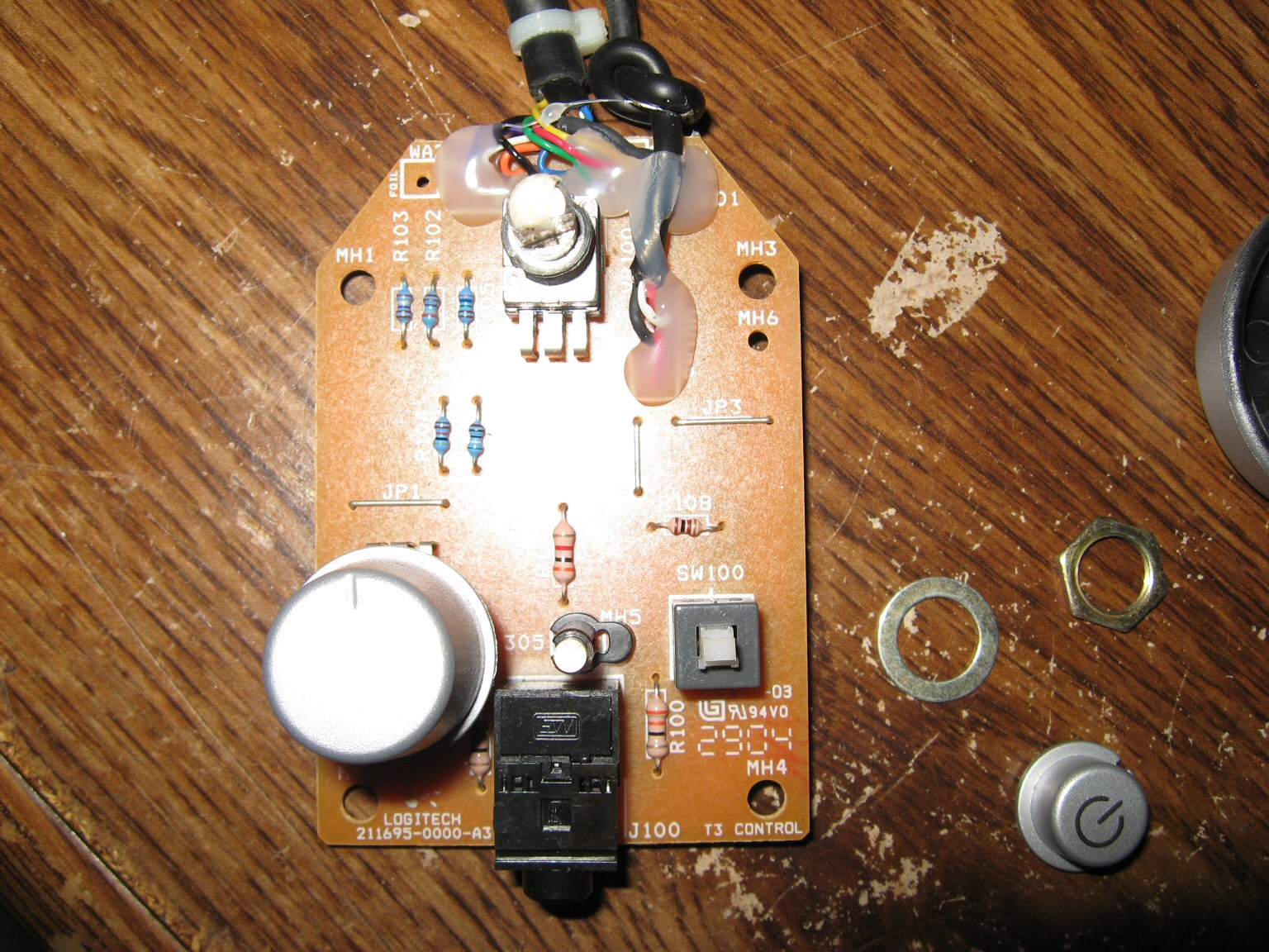

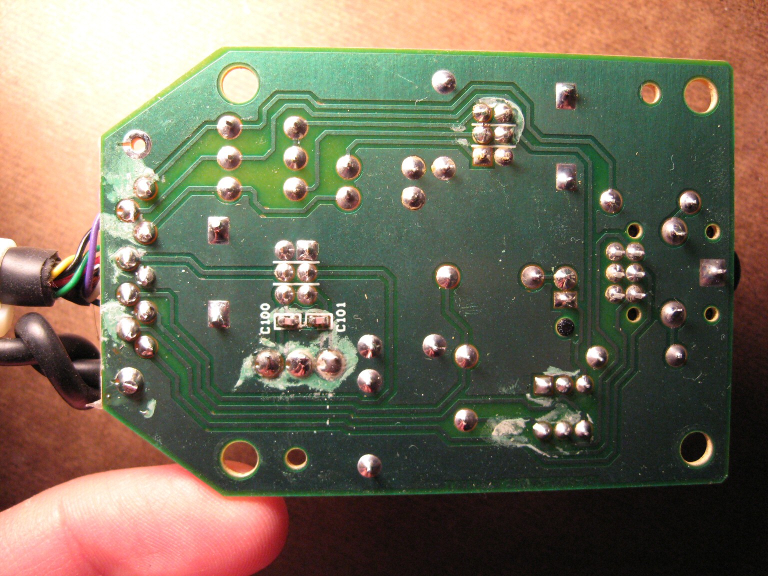
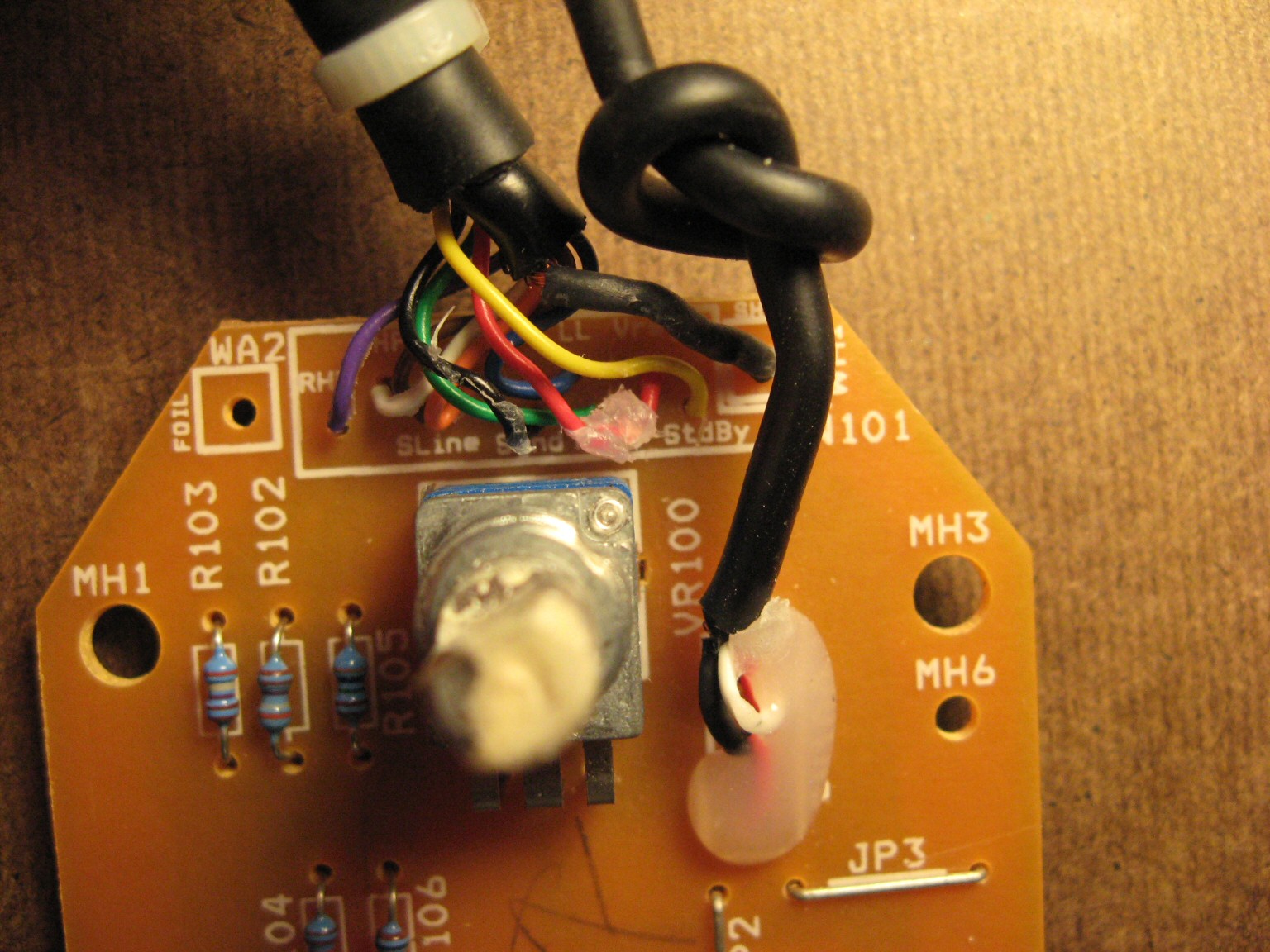
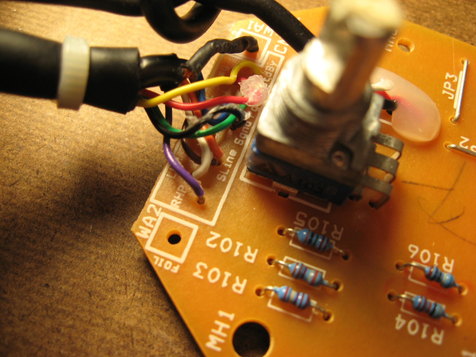
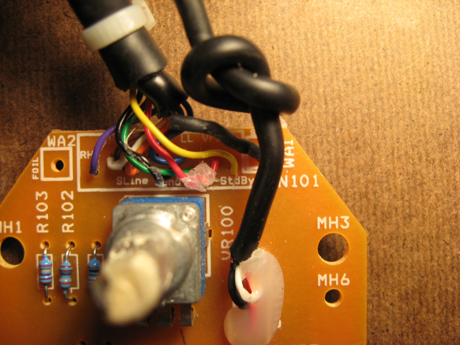
The PCB silkscreen provides wiring labels for all 9 wires (plus 1 shield “wire”). Of course, you’d have to open the pod up yourself and use a continuity checker to find out which pins of the High Density 15-pin D-Sub connector these wires go to. Lastly, I can verify Logitech’s claim that standard VGA extension cables should not be used with Z-2300’s. The center row of pins for a VGA extension cable are all tied to ground. Logitech uses a single pin in this row for an audio signal. Anyone attempting to extend the interface cable should make sure to use a pin wired 1:1 (that is, pin 1 is wired to pin 1, pin to goes to pin 2, etc., and no pins are tied together).
EDIT (April 27, 2010) – SCHEMATIC RELEASED!
DISCLAIMER: This design is for personal use only. Information is provided without warranty, either expressed or implied. Schematic and information below may contain intellectual property of Logitech.
Someone by the name of “HxCxK” independently uncovered and released a rendition of the Z-2300 schematic last month. Since he has let the cat out of the bag, below is what I originally found:

Miscellaneous schematic notes:
- Resistor R108 omitted (serves to buffer supply rail into standby pin; not critical)
- Potentiometers not measured (10k parts are common and work well in this circuit)
- Capacitors C100, C101 are optional. Someone with more free time may wish to investigate the frequency response with and without these parts.
Principles of Operation:
- A stereo audio signal comes in through the green 3.5mm connector.
- Signal passes through the remote’s main volume potentiometer for attenuation.
- Signal is then fed down to the subwoofer enclosure for pre-amplification.
- The pre-amplifier(s) distribute the audio into two places:
a) To the left and right satellite amplifier (and subsequently to the 2 speakers)
b) Back up to the remote. - Inside the remote, the signal is split again:
a) To the headphone jack
b) To the subwoofer potentiometer (where it is combined to mono at this point) - Output from the subwoofer potentiometer finally gets fed back into the enclosure and last, into the subwoofer amplifier.
D-15 Connector Pinout:
| Pin | PCB Name | Description |
| 1 | SLINE | Subwoofer Line Input |
| 2 | (unused) | |
| 3 | SGND | Signal/Audio Ground |
| 4 | PGND | Power Ground |
| 5 | STDBY | Standby, Active Low |
| 6 | RL | Right Line Input |
| 7 | (unused) | |
| 8 | (unused) | |
| 9 | (unused) | |
| 10 | (unused) | |
| 11 | RHP | Right Headphone Output |
| 12 | LL | Left Line Input |
| 13 | LHP | Left Headphone Output |
| 14 | (unused) | |
| 15 | VREG | 15V Supply Rail |
See images above for connector numbering. Those who wish to quickly test their Z-2300 can ignore most of this. The Z-2300 switches on when Pin 5 is connected to Pin 15. Then, apply audio signals as follows:
Pin 12: Left Input
Pin 6: Right Input
Pin 1: Subwoofer Input
Pin 3: Audio Ground
Printed Circuit Board:
The board can be purchased from BatchPCB in unassembled form. This is entirely non-profit. As such, NO SUPPORT IS PROVIDED. You are on your own.

Top View of Board

Top Copper Layer

Bottom Copper Layer
Parts List:
| Reference | Part Description | Part # | Qty |
| J1 | STX-3100-3C | 806-STX-3100-3C | 1 |
| J2 | STX-3100-9N | 806-STX-3100-9C | 1 |
| R102, R103 | 2.85k resistor | 271-2.87K-RC | 2 |
| R105 | 3.62k resistor | 271-3.6K-RC | 1 |
| R104 | 4k resistor | 271-4.02K-RC | 1 |
| R107 | 10.2k resistor | 271-10.2K-RC | 1 |
| R100, R101 | 33 resistor | 271-33-RC | 2 |
| R106 | 591 resistor | 271-590-RC | 1 |
| U2 | Alps RK0971221Z0 (10k, Volume) | 688-RK0971221Z05 | 1 |
| J3 | ICD15S13E6GV00LF | ICD15S13E6GV00LF | 1 |
| U3 | Alps RK09712200MC (10k, 15mm) | 688-RK09712200MC | 1 |
| LED1 | 3mm LED | 1 | |
| C100, C101 | 0.01uF Multilayer Ceramic Capacitor | C324C103K5R5TA | 2 |
| [Cable] | Male to Female, HD, 15-pin D-Sub | AE1380-ND | 1 |
Hi John, i have a question regarding the control pod.First my issue is that i do not get sound from the left channel both speakers work though on the right channel normally.Subwoofer is also working.Only if i turn the volume to the max i get some slight sound from the speaker.So according to the principles of Operation( 4.The pre-amplifier(s) distribute the audio into two places:
a) To the left and right satellite amplifier (and subsequently to the 2 speakers), could my problem be on the amplifier or the problem is more likely the control pod.What is your thought?Thanks.
That’s likely a mechanical problem. What happens if you wiggle the 3.5mm audio cord?
I did wiggle the 3.5mm cord on the control pod and also on the end that connects to the soundcard.Nothing happened.Like before i can hear the sound coming from the speaker connected to the left channel jsut slight if i crank up the volume.I even opened the pod so i can wiggle better or to see if something isnt connected all seemed normal.I also measured the resistors on the pod according to the color code.The values seemed normal(so i far i saw , not an expert).When you say mechanical problem what you mean with?Should i open the subwoofer box to take a look for some wear on resistors?Thanks.
By mechanical, I meant audio cable, audio jack, or potentiometer. There is no audio jack, so it’s probably a bad cable. It’s very unlikely that the amplifier itself has failed.
Hi John,
I seem to have the same problem George G did above. Is it possible for you to explain to me what he did to fix it? I’m a complete novice when it comes to this stuff so if you could be thorough, that would be great. Thanks a lot!
Hmm ill take a look on the jack that connects to the soundcard.Probably i will plug in a new jack and solder it.The cables look ok no cut or anything else visible.Hope it works.I let you know the outcome of it.Might be helpful for others too.
Hi George,
I seem to have the same problem you had. Can you please explain in detail how you fixed the problem? I’m not too familiar with the inner workings of the remote pod. To clarify, both speakers work if I plug them into the LEFT jack on the sub. Also, if I wiggle the 3.5mm jack that’s in the computer, it does work, but then goes out.
Any help would be appreciated – thanks a lot!
Well i did fix the issue.Problem was the cable that connects to the sound card from the pod.It didnt had a visible sign of wear but still it was problematic.So thats it.Thanks again for your input John.
Hey I also have a z 2300 and was starting to get a short with the 3.5 mm cable that leaves the pod and connects to the PC..sent it by someone to repair and all he did was change some speaker wires for thicker ones and now one of the channels isnt working at all!
I was giving a RCA Y splitter to use to get sound on the 2 satellites from one channel :S
Is there a way to fix this? Or can I order a generic control pod from you all? it’s very annoying that I have to listen just one channel 🙁
Thanks for your help!
Hi,
My Z2300 power supply cord when connected to mains with the switch on remote in On position has created some problem within the unit, it won’t power on. I can see that when I connect the plug to mains some light sparking showing that the unit is drawing power, but the remote on/off switch does not respond. Can you suggest some check list/Points that can revive my unit. I have already checked the fuse it is fine
Hello Dont know if anyone is reading this but will give it a try. I have a Z2300 system aswell but the jack started to play up. i cut the wire and reconnected them which solved the problem for a while. i have reattached the wires without solder now for abou 3 months and now it has come to the point where i have no wire left at the loose end (jack end not control end). I would like to know if there is anywhere i can get a jack with wire to reconnect it and have a system that works again.
Thanks
ineedfixin.com
My sub is is not making any sound at all. I tested the sub woover and its good, could the problem be the remote? Remote works well,volume works,both satilites works. Could i test somehow if it is the remote or the pcb(amp)
Thanks
Can anybody please tell me where I can buy 1 of these?
got the same problem!
i was thinking to trow it away, but maybe its replaceable.
i tought i was the only one with this problem!!
Hi, do you perhaps sell those Z2300 controls or know where I can get. I have e-mailed iNeedFixin as well so I’m waiting for their reply.
I am in South Africa so if you do sell them would you ship here?
Regards
Rudi
Hey, I accidentally dropped my laptop onto the control pod, and it smashed in the bass boost, shattering the board. How much does it cost overall to build this?
Hi!
I just wanted to say thanks for the board and schematic!
I made a quick video while putting it together: http://youtu.be/tzqT5nAUXZo
Also, I have an extra board and parts. If anyone wants one, let me know!
Alvaro
Hi John. I have a working set of Logitech z2300 speakers and sub, control pod is working well. I also have an extra z2300 sub. If i purchase a HD DB15M To 2 X HD DB15F, Y splitter (http://www.alphacity.co.nz/index.php?main_page=product_info&cPath=174_651&products_id=19381&zenid=894626cfdcbeecab3c1d94694f1e06b6), would I be able to split the signal to the 2 subs? If not I will just buy a bypass cable and split the signal at the 3.5 output jack from the sound source. But I’d like to be able to use the pod control for both. Thanks.
@Geoge G
Thank you very much for your tip i had the same problem with my z2300
And i changed the jack (which also seemed to be in good condition but my left speaker was really low while the right one will sound just fine ) that conects from my laptop to the pod and now its working again!!!!
Thank you!!!!!
Hey,
Any idea where to source the speaker in the remote units? My right unit stopped working — lines are good all the way to the speaker. Channel is working (switched speakers to check.) Case and cable are in excellent shape, speaker just quit.
Thanks for reading, even more if you can suggest a source to buy just the internal speaker.
Aloha,
m a r
Hello John. My Z-2300 speakers and subwoofer work fine – long as headphones aren’t plugged into the controller jack. With phones, one channel continuously cuts out, and I must rotate the headphone wire to get both. Also, bass adjustments aren’t noticeable through the headphone jack either. Does this sound like a new remote would solve the problem? Also, can the new remote be put in the old housing, or is it ok to just stand alone? Thanks in advance.
I was really hoping to now have to disass. and reass. my remote if not necessary, so I have a couple questions. Since I’m happy with the way the factory remote seems to work I was wanting my additional controller to work as similar to that as possible. You say that you didn’t measure the pots resistance so do you think that the 10K pots worked in practice the same or very similar to whatever the Logi remote used? I was looking at HXCXK’s version and he uses 5K pots. His bass circuit has different resistance values so that may allow for 5K pots but the volume controller circuits are the same otherwise. So it seems like his will likely operate much differently and may not even bring the volume down to inaudible levels at minimum. What do you think about using 5K pots? Also the schematic is a little blurry and I’m lost on the wiring that comes off to the right beyond the LED. I can see from the PCB that what it does is interrupt the voltage to pin #5 when the headphones are plugged in, is that correct? I know that one wire goes to pin #5, but what is the other branch and what is the rest of that whole wiring branch consist of? I want my remote to have all of the functions of the original. Thanks for your help.
So I recently came across this blog and i have no idea how to build these. is there any place i can purchase a new remote? willing to pay alot
No one’s building these right now. There are a couple genuine Logitech remotes on eBay right now for ~$50, so you might as well go that route.
I have a z2300 and i get no sound from my system….power is good but no output…..not even sound when headphones connected to remote….please help….
Thanks for the great info!
My left channel has been unreliable. When I turn the volume potentiometer the left channel crackles in and out (but mostly out). I have temporarily fixed the issue by tying together two of the potentiometer pins so the left channel bypasses it. This does the trick pretty well. Someday I’ll get around to doing a more permanent fix.
Hi there, can you post a photo how did you managed to fix your control pod?
best regards, Kyle
So I just ordered 2 of the PCB boards. A friend of mine gave me a set of the Z-2300 so I am going to attempt to do this fab. Just to be sure when you designed the new board it is still not designed for a VGA cable, but a 15 pin straight through or 1:1 cable correct. And 2. do you have any suggestions on good case or some way I can get a black brushed aluminum case for it. Thanks for your help and all the work you put into helping all of us out.
Hello,
First thanks for providing this info.
My controller pod has started to fritz out due to bad audio jack. I purchased the batch pcb boards and the parts to build one but it isn’t working. I am wondering if all components need to be included for it to work. In my case I omitted the headphone port and the led because i don’t need them, but are they needed to “close” the circuit for this controller to work?
thanks for the quick reply John, is there a part number for the heaphone connector? I dont see it listed anywhere above.
Thank you for this post. It is by far the most intelligent post I’ve read, even thinking about the rights of Logitech. I am going to assemble my own board based on your work here, Thanks again.
Looking at the above schematic, correct me if i’m wrong but surely the original remote volume didn’t start at full volume and rotating it clockwise turned down the volume. Iv’e never owned a Z-2300 until now and need to build a remote as it is missing!
The pot wiring looks backwards, but it’s correct. Potentiometer at fully counter-clockwise position yields minimum/muted volume. Fully clockwise position yields maximum volume. The schematic was generated exactly as observed from an original board.
jseaber thanks for the information, it’s just I was taught that the arrow indicated clockwise direction of the wiper or a dot (if used, indicated wiper at full clockwise end of track) my thanks to you for your speedy reply!
Regards
jseaber, sorry forgot to ask you is the sub volume pot 10k log on lin?
Regards
I just stumbled upon this page and found a lot of help here. Do you have a tutorial of how one might put this new pod together? I am an amatuer when it comes to this stuff but this seems to be the only solution I can find.
Hi, this is Mario from Argentina, does anybody know if Z5500 control pod could work for Z2300?
Hey looking to do this for my Z2200 i assume it’s near the same? my left channel died this morning from abuse of the jack in the front :(.
Great tutorial but I am having an issue with a different set of speakers, it is a z-640 which was a gift many years ago. The problem i am having is with the headphone jack itself and it needs to be replaced, any idea where one can be purchased so that i can solder it on to the board and get my speakers back.
Thanks
Just wanted to say thanks. Was having this balance problem where the left speaker is a lot more louder than the right speaker. Lowering windows volumes and using the remote control volume thingy instead worked.
Wow talk about bad timing I clicked the add to cart button for this board today 5/1/13 and found out that BatchPCB closed up shop yesterday (4/30/13). I was able to fix my Logitech 2300 controller but I’m sure it will crap out on me in the near future. If anybody wants to get some of these boards made at OSH Park I’ll go in on the order.
what if I put a 9.1K resistor instead of 10k?
That’s the LED, correct? You can put just about anything here; this sets brightness. Just keep the current between 1mA and 30mA (too dim, and way too bright, respectively).
V = IR
R = V/I
V = 15
R(max) = 15/1ma = 15kohms
R(min) = 15/30 = 0.5k = 500 ohms
Thank you for this tutorial.
I had to replace the bass potentiometer, i took the ALPS RK09L12D0A1T which looks similar to the original one.
It’s working well but the shaft is a bit too high and there is no center detent.
i have z2300 and i want to use it to my denon av receiver as stand alone subwoofer ,my denon subwoofer has a bass pre output and the sub also has an inbuilt lowpassfilter inside so the frequencies coming out are very low so what should i do?
You don’t happen to know anywhere else that could supply the board now considering BatchPCB closed down?
I may have a few boards still.
Hi!
I’m interested in one of your boards. Email me if you still have one for sale!
PCB is easy to make using Double-Sided Prototype PCB. Just connect the lines by soldering a small copper wire to every component. I’ll post my work as soon as I finished mine.
Hello
I also own the Z2300 speakers and it seems that my volume-control potentiometer, is at its last days. Sound from one of the speakers disappears, and it is not controlling the volume as it should be.
After looking at the pictures and reading the article i decided to replace the potentiometer it self, without making a complete new control-unit.
Can you please help me with the details on the potentiometer??
I’m looking for a 8-pin, 10K, Linear pot??
Right?
Thanks a lot !
You’re looking for a dual-gang pot, which will have 3 pins per gang = 6 pins total. The two extra “pins” are for mounting only.
This guy *might* fit:
Alps RK09L12D0A1T
http://www.mouser.com/ProductDetail/ALPS/RK09L12D0A1T/?qs=sGAEpiMZZMtC25l1F4XBUyOcKw5CnqLBo6T7Dq211pk%3d
Thanks!!!
Did this work?
Thank you very much. Which kind of resistors would fit my needs? I also thought using software to equalise the sound instead, but I suppose that noise levels would be higher.
Any 1% metal film, 1/8 or 1/4W size will work. You’ll have to experiment with values. Start in the 1k-10k range. No higher than 100k.
This values will work for both bass (subwoofer) and mids-highs (speakers), won’t it?
Thanks a lot for the assistance.
These are ballpark values to experiment with. Yes, the ranges are valid for both volume and bass sections for testing.
many thanks for the research you made. I lost my control and I am building mine. GBU
I can’t be purchased the pcb board because the website doesn’t exist. [Internal Server Error (500)]
May I ask you If exist other website alternative.
[original link]
http://www.batchpcb.com/product_info.php?products_id=32413&check=69052ae160646b44dfed92de8fb92c6f
http://www.ineedfixin.com does not work
I concur, I also cannot seem to also reach this link, there was a problem loading the page, according the Firefox resultant; the server cannot be found.
I concur, I also cannot seem to also reach this link.
Hi
I tried with four pins are introduced to clarify the speaker, but did not succeed.
Please guide.
Does anyone has the circuit schematic for logitech Z-4 Subwoofer?
Hi. Did you find something for the Z4 ? I’m also looking for one … Thanks!
I’m also interested in the Z4! I lost my remote control and would buy a new one from LG, but they are overprized or only available in the US… I found this instructions for a “Logitech X-230 Subwoofer cable pinout”. May be there is the answer? what does the experts say?:
http://pinoutsguide.com/Home/logitech_subwoofer_pinout.shtml
muchas gracias…
I have two z-2300s. One powers the left spkr, the other, the right. I have the volume control on both cranked to max. and control the overall volume with a Mission preamp. The question I have is, does the preamp in the Z2300s negate the higher quality preamp of the Mission since they (the Z2300s) are down stream of the Mission?
thanks for all your great information,
Bill
@Bill: Yes, gain of the Z2300 preamp is high and adds audible noise, so I image it’s defeating the quality of your external preamp.
Thanks for the fast reply. You had to have known this was coming at you next …. is there a way to disable (not even sure if that is advisable) the pre-amp in the z2300s? Also, is it possible to bridge the amp in the Z2300?
See what you’ve started by initiating this blog?
best regards,
Bill
The satellites and sub use TDA7295/TDA7296. It’s electrically acceptable to bridge the chip. The datasheet discusses 4 ohm loads, and even shows a 2.7 ohm example load (approx. bridged 6 ohm speakers): http://www.st.com/web/en/resource/technical/document/datasheet/CD00000198.pdf
Keep an eye on temperatures. Logitech uses a massive heatsink, which I suspect is overkill and will probably handle a bridged load. But I could be wrong.
Yes, you could bypass the preamp and wire input signals directly to the chipamps. Hacking required, of course.
Hi can you tell me how to bypass or the pinout of a bose companion 3 serie 1. The person that give It to me lost the control pod and i am working on how to turn It on so if you have someting that can help mi i whill apresiate It. thanks you for your time.