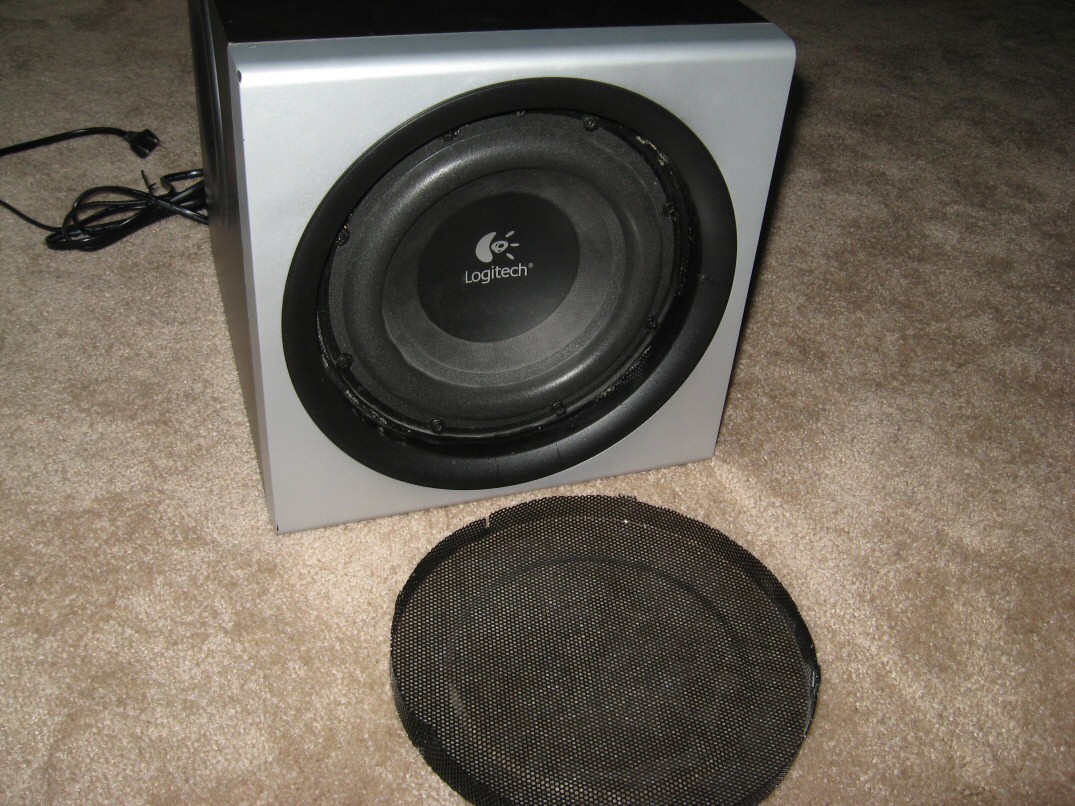
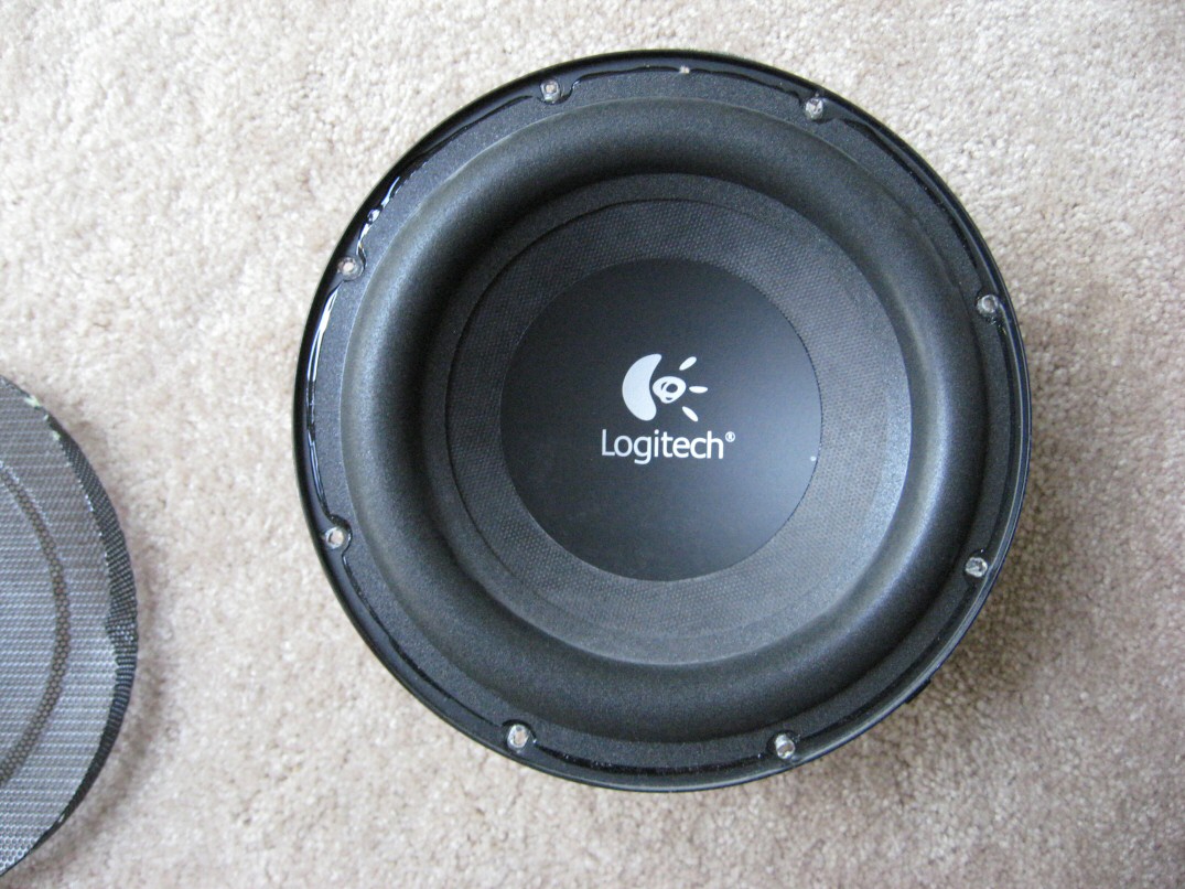
Curiosity inspired me to take apart my Z-2300 subwoofer. The grill pried off without much difficulty, and I was even able to reassemble it with minimal cosmetic damage.
WARNING: Perform this disassembly with extreme caution! The enclosure contains a 120V AC transformer. With the Z-2300 turned on, unplug the power cord and wait for the power LED to fade. This will drain the capacitors and minimize the possibility of shock.
Various facts discovered:
- Subwoofer uses an 8 screw mounting pattern
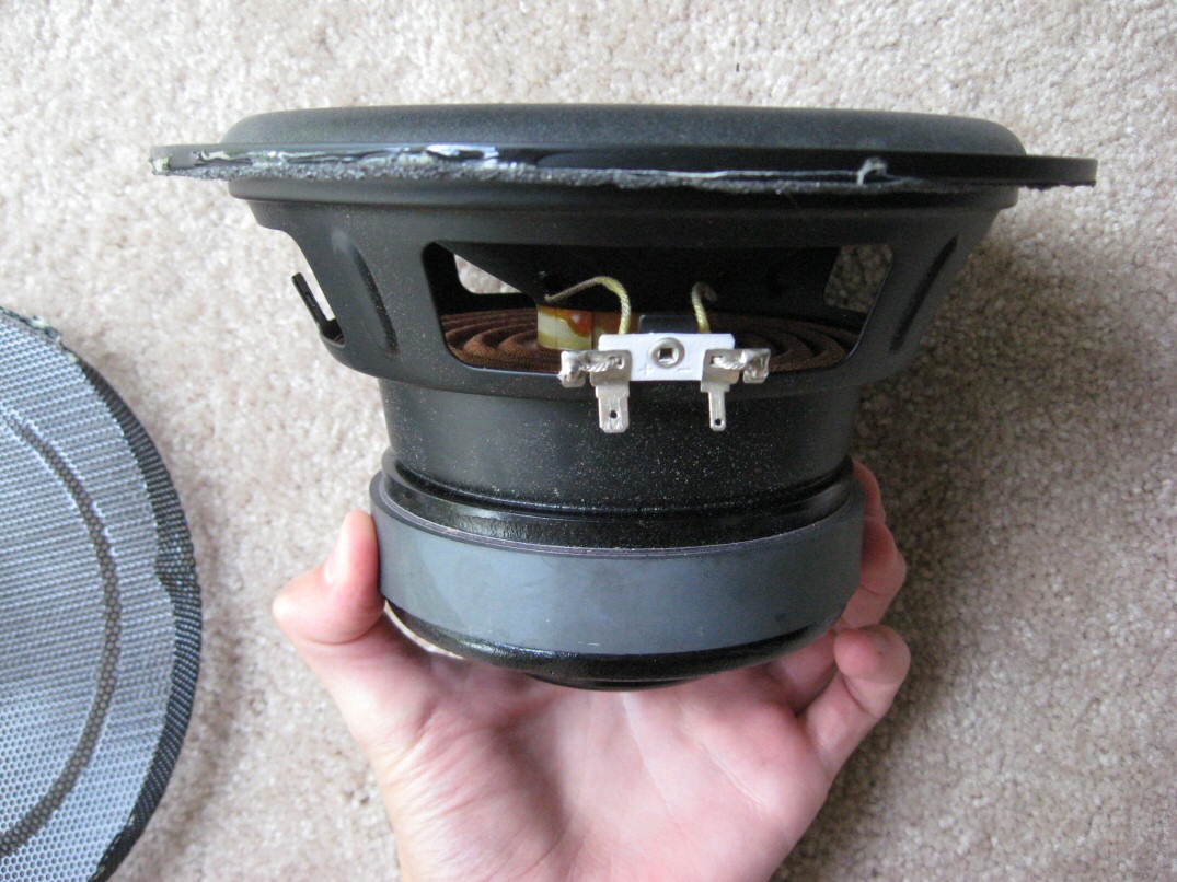
- Subwoofer impedance measured at DC: Single voice coil, 6.5 ohms (8 ohms as per specs)
- The amplifier had no problem driving an external 4 ohm subwoofer in a separate enclosure.
- Subwoofer construction: Corrugated paper and foam surround.
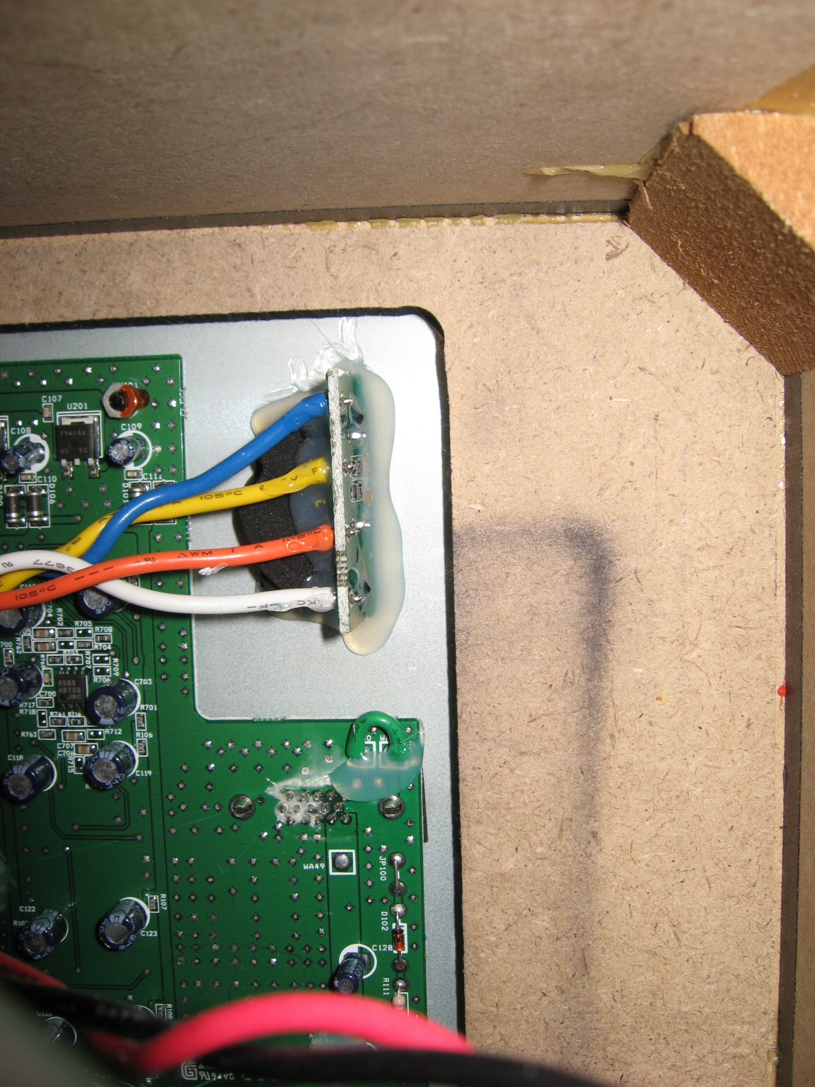
- Logitech Model #: W200OF120-02F
OEM: Tang Band W8-670Q
- Logitech Model #: W200OF120-02F
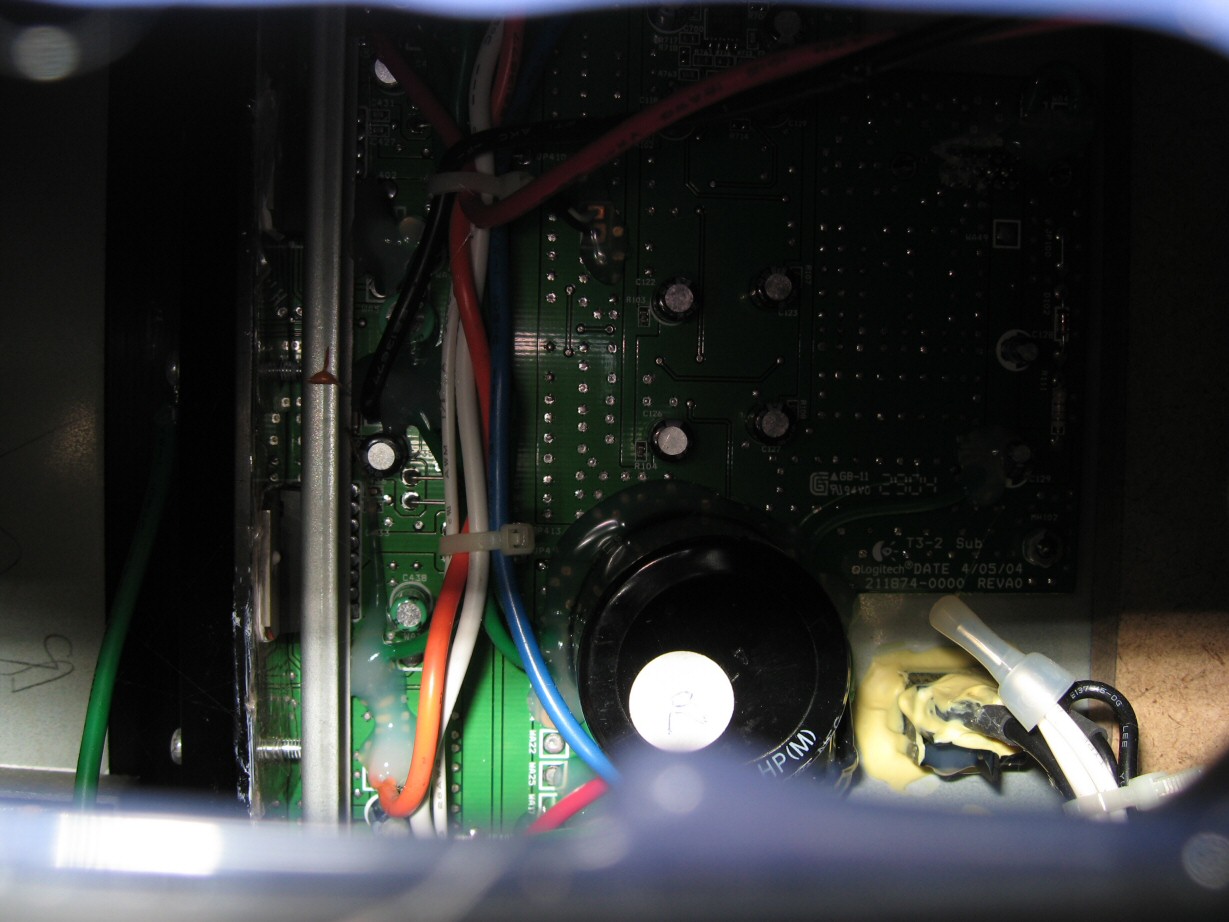
- The Z-2300 uses a JRC4565 operational amplifier for pre-amplification and an unidentified chip amp for output amplification
- EDIT: Satellites and subwoofer use TDA7296 and/or TDA7295 Class AB amplifier IC’s (identified by judeh101)
Potential modifications:
- As others have done, the enclosure could use some sound dampening material.
- Replacing the subwoofer with a better made 8″ woofer (polypropylene cone and rubber surrounds) would probably improve sound quality. The amp can handle 4 ohms (based on my limited testing), which means output might even be stronger with such a woofer. However, the amplifier’s 150Hz crossover is fairly high and should ideally be reduced to below 100Hz. If I get around to replacing the sub, I’ll figure out the amplifier circuitry and post that modification.


Thanks for your great information on your blog.
Do you know if the internal power transformer converts the 230V AC to 12V DC? Or is it some other DC voltage the amp is powered on?
The internal voltage is higher than 12V. I do not recall how high, but others have mentioned the answer elsewhere.
Okay thanks. Do you know anyone or any site where I could find a description to use the Z-2300 on car voltage (13,8v with running engine)?
It would be weird to invert the 12v DC to 230V AC and again back to something about the 12v DC (internal Z-2300 power voltage)
I’m not aware of such a tutorial. Amplifiers are generally dual-supply devices, meaning they require a positive supply rail as well as a negative supply rail. Even if you boosted the voltage from your car’s battery/alternator, you’d still need to produce an equal and opposite (inverted) voltage.
The easiest solution: Stick with an AC-DC inverter and let the Z-2300 generate the voltages it needs.
Hey jseaber,could you please help me with figuring out the crossover circuitry in the z-2300 because i’ve modded my old z-2200 pretty hard.I’ve added some old JVC SP-E5 speakers and changed their tweeters,also i’m using the Z-5500 box and woofer,and i did the remote control mod on youtube(the one that allows you to turn down the woofer to 0%).But i’m kinda frustrated with the big boom on 150~hz that the woofer makes i want to use the 8″ bass drivers on the satellites to do the job but they go around 200hz and then start to fade in sound which kinda sucks.I want to try and change the woofer’s crossover to 100hz or something around that please help.
I still haven’t gotten around to that. The circuitry is inside of the subwoofer enclosure. For now, you can try creating a low pass filter on the subwoofer signal before it gets to the subwoofer pre-amp: Open the remote and place a capacitor between P1 and P3. A schematic is provided in my Remote Control Pod Disassembly post. You’ll have to experiment with the capacitor value.
won’t that create a gap between the subwoofer and satellites ? And is there a way to calculate the value of the sub ?
No, the satellites have already recieved the signal. “SLINE” (the subwoofer signal) is the last signal to be created, so the addition of a capacitor will create a low pass filter only on the subwoofer input. You’d need to know the input impedance at P1 to make any reasonable calculations, then the equation would be:
f = 1/(2*pi*R*C)
where:
R = resistance at P1
C = low pass filter capacitor
I actually thought of doing that but not in the remote.I thought of doing it on the subwoofer negative cable,However i decided it’s not worth it since that would only create a gap between 150-200 which is even worse than the boomnines of the sub
I don’t mean that the capacitor will create a low pass filter also on the satellites.What i mean is that the subowoofer would be prevented from playing up to 150hz and since the satellites are cut from around 150-200 there will be no device producing these frequencies.Or there is something i’m missing ?
Do we know for sure that the satellites have a high pass filter at the same frequency? If so, then yes, there would be a gap.
I’m using Polk R15 bookshelf speakers on my only Z-2300 set and the bass/midbass can be overbearing. We keep the subwoofer turned down to less than 25%. I assume Logitech implemented HPF’s on the satellites, but they may not be set at the same frequency as the subwoofer’s LPF (150Hz). This is just conjecture based on my ears, so correct me if I’m wrong…
That’s kinda true i guess :).The thing is i have two old jvc speakers with 8″ rated down to 60hz and the their power starts declining at 200hz so i guess they have a crossover
Thank you very much for the information .Can you please tell me the amplifier chp number
The JRC 4565 opamp is the only chip I was able to identify. Sorry, this was done almost a year ago and I no longer have a disassembled Z-2300.
the actual amp is tda7296 (both for the satillites and sub)
the opamp for the headphones are jrc4565
jseaber, do you know how to remove the subsonic filter?
Looking at the TDA7296 datasheet, the “subsonic filter” is really just a safety mechanism to prevent DC offset. The low frequency cutoff can be flattened out by increasing the values of C1 and C2 (see Figure 1 in datasheet). To eliminate the subsonic filter, C1 would need to be shorted out or replaced with a small resistor. However, this could be very dangerous if source DC offset exists. I’d suggest increasing the capacitor values by up to 10x, if feasible.
Keep in mind I am basing this answer purely on the TDA7296 datasheet. I have no Z-2300 board on hand to verify that Logitech actually used the circuit given in Figure 1. The Z-2300 implementation could very well be different…
I’m not even going to pretend that I know all the preceding tech chat. I simply need to know … can I hook up a pair of 6ohm speakers to the amp without any damage to any of the components?
thanks,
Bill
Yes, 6 ohm speakers will be fine. The TDA7296 is specified for operation down to 4 ohms.
Thanks jseaber.
Thanks jseaber! I’m gonna give it a go, if I blow the amp, I can replace it, no biggie. 😀 thanks for looking at it in details
btw, when you said “increasing the values” of C1 and C2, does that mean I have to get a capacitor with a higher farad value?
@judeh101: Yes, higher farad value. And make sure to use the same capacitor type as the originals, or something superior. High voltage (100V+) polypropylene film types are best for this circuit; polyester films will also be fine. Avoid electrolytics/ceramics/tantalums.
And again, Logitech’s circuit is likely different than the typical application circuit in the aforementioned datasheet. At the very least you should expect a different naming scheme on the Z-2300 board. Different component values are also possible. I do expect you to find “C1” and “C2”, though (whatever their names may be). These are important elements of any consumer grade amplifier circuit.
yup, I have to find pin 7, 8 then look for the electrical path leading to the capacitors.
Thanks a bunch jseaber, you’ve made this so much easier for me! are you an engineer?
Electrical engineer, yes.
perfect, I opened the z-2300 up and indeed it’s exactly the same as the schematics on the tda7296 😀
I think I’ll short out C1 and see what it’ll do. is it ok to leave on the capacitor when I short it out? (the cap looks like a small resistor)
Yes, that should be safe as long as the audio source has no DC offset (it shouldn’t…)
jseaber, sorry to post so much, but I also opened up my older sets of z-2300 and found something interesting… It has a mix of both TDA7295 and TDA7296.
That is interesting. The TDA7295 and TDA7296 are pin compatible. No changes are required to the amplifier circuit, although the ’95 can be fed more voltage (20W higher output), so those Z-2300s might also have a beefier transformer and associated buffering circuitry (or not). Performance is slightly better from the ’95, but neither looks that great. THD skyrockets beyond 30W and 40W output on the ’96 and ’95, respectively. They’re already well beyond 10% THD before reaching their “High Output Power” Ratings. TDA7295 is a slightly superior chip. If the power circuitry is up to par, you should find that Z-2300 to slightly outperform the other.
This looks like a financial decision. In lots of 10,000, the TDA7295 is $0.27 cheaper per chip than the ’96. That’s a very easy way for Logitech to cut costs.
alright so I attempted to jump c1 and my amp wouldn’t play anymore. It’s gone. Jumping C1 isn’t a very viable solution (you’re right).
I wouldn’t expect jumping C1 to kill the amp (if anything, DC offset would’ve killed the speaker). Are you absolutely sure it was the right part?
The chips have short-circuit protection, so hopefully it can be revived. Just one channel is dead, right?
yeah, just the subwoofer amp (the middle two). My amp is actually dead, I’ve tried everything I could to get it back working, but it’s gone alright. 😛 The short circuit protection probably didn’t work too well
Have you checked the fuse?
yeah, the satillites work, just not the sub. It’s ok, I just bought another z-2300, and I’ll use this broken one as my project. 🙂
I’ve just found something interesting!
I opened up my z-2300 satellites (cause I was so bored), cut open the fake ports on the satellites. And guess what? The mids and 140Hz-200Hz is audible now.
These satellites sound awesome after being ported. I’ve also stuffed cotton (kind of like the same principle as sealed enclosure)
may i hav clear circuit of z2300 for subwoofer filtering from left,right signals ?
The closest you can get is the TDA7295 datasheet (see links above).
Hi, i have the logitech z-2300 with straight satelites, the newer model i think, it’s diferent from that video u post jseaber and the right satelite doesn’t work. The satelite woorks on the left channel but not in the right and i thik the amplifier it’s the problem. What TDA is in my model?
[img]http://www.pacificgeek.com/productimages/xl/970118-0403-R-2.jpg[/img]
As mentioned in the video, the speakers used for testing were not Z-2300 satellites. I believe they were part of an older Z-540 set. You’ll have to open the subwoofer to determine which chip your unit uses (they should be interchangeable, by the way).
The TDA you have mentioned are from a Z2300 subwoofer right?
how do i get to the bord? by taking the subwoofer off or from the back by unscrewing the aluminium block?
Yes, this entire article pertains to the Z-2300. Try removing the rear heat-sink.
ok jseaber, thsnks. By the way i’m from Romania, i don’t now if you heard about it but thanks, i also have this passion to reapair things and i want to fix the output from the right channel. I’m sure that is burned.
No problem, Sanz. Have you checked the remote? The amplifier could very well be the problem, but it’s also possible that the remote is to blame.
The remote? do you meen the wire, the volum buton?what from the remote? Did the circuit from the amplifier has fuse for each channel speaker or for all 3 channel one fuse? i think maybe is the fuse but i don’t think so. At this sistem one SMART GUY had connected 2 ore 3 speaker on the right channel at once!
Hey I have a quick question. I wanted to know if I can replace the original subwoofer with the Kicker 07C84 (http://amzn.to/cBaTFA) or the Kicker 10C84 (http://amzn.to/aaywTi). They are both single voice 4 ohm subs with a range from 100 watt RMS to a peak of 200 watts. Would I be putting a big amount of stress on the amp or would this work?
Thanks.
@Steve: Yes, the amplifier chips are rated to handle 4 ohm speakers. I tested one for a few minutes and had no problems. Go for it and let us know how it works in the long run.
Thanks man. I’ll give it a try and hopefully be able to post it on youtube or something. I’ll let you know.
From the Logitech website i found out that Z-2300 have two model generations
1) M/N: S-0118A
2) M/N: S-0118B
This numbers are printed at the back of the subwoofer.
judeh101 and jseaber can you confirm that which model number have a combination of TDA7295 & TDA7296 chips.
I assume M/N: S-0118A have 2 X TDA7295 & 2 X TDA7296 chips whereas M/N: S-0118B have 4 X TDA7396.
Hey,
Can you help me with hooking up z-5500 transformer to an external amplifier?I bought a 2.1 TDA7294 board from china rated 2×80 sat. 1×160 sub.And i want to hook up my two satellites and the z-5500 sub to the board.But i don’t know how to wire the transformer.The schematic on it has two blue wires which are supposedly 0V and 14.5V and one orange 26.4V one black 0V and one yellow 26.4V.The amp has i believe two ways to be hooked up?it has a 26-0-26 AC input for a transformer and a rectifier thingy which has a + two ~ ~ and a -.I tried to hook it up to the 26-0-26 and one of the chips on the board burned of(literally).What i did is i connected the two(red and yellow)26V wires to the 26AC inputs and the black to the GND input?Can you help me.I’ll experiment on the burned out board and get another one if i get it to work somehow.
Thanks in advance.
actually when i see the board paths the 26v cables i connected from the transformer go right into the rectifier,so i didn’t make a mistake ?
Actually i might have wired them correctly.Although i don’t know why one of the chips burned out?When i look at the board’s paths where the 26-0-26 ac conncetors are,the paths from the connector are leading to the ~ ~ of the rectifier and the gnd is leading to the – of the capacitors.Maybe the transformer has gone bad?I forgot to mention that the z-5500 i got it from keeps blowing the fuse but when i disconnected the transformer from the board it stopped blowing it.
What is the VA rating of the toroidal transformer of Z-2300?
what is the amp rating of toroidal transformer of Z-2300 ? shall i hav a sub filtering circuit of Z-2300?plss..
Hi Jseaber,
Thank you. You have shared good information on this page. I was able to accomplish something and I want to share with you and everyone reading your page.
I took the risk of of exploring the z2300 to the next level and separated the amplifier board from the sub’s back metal plate. I found four NJM 4565 opamps and I believe those four are acting as active frequency filters. one for each satellite and I’m not sure what the middle two are for (since the sub line is already mono from remote pod).
I managed to cut the input to the two TDA7296 amps and connected a wire with 3.3k Ohms (arbitrary value) straight from D-SUB pins 11 and 13, left and right channels respectively. Now my satellites are sounding at full range. I’m using a pair of Wharfedale diamond 10.SR and I don’t think the company would expect me to use low freq protection for their speakers. I’m quite confident that the wharfies can handle full range. Applying a first order low pass in my control pod lowered the subwoofer cutoff to the lower limit of the wharfedales. Now my Z2300 really sounds great. It’s even clearer than the stock system and no more peaks at 60-80Hz.
Just a disclaimer, if ever somebody tries or improvises what I’ve done, please be careful and please don’t blame me for any damage. I’m just trying to reach out here so we can all be happy. =)
@Von you are brilliant! kudos! I would love to reduce the crossover of my z2300. I have M-Audio av40s in place of the z2300 satellites and the z2300 sub of course, as a setup. However i do not know how to carry out the operation you described, i’m also not really confident enough to solder and do not have a soldering iron (if that is needed). maybe i could try to find someone near me who knows how to do something like this…
Thanks Elliot! You have some nice bookshelf speakers for your satellites! Do you connect your av40s to the rear of the Z2300 sub? since your satellites have their own amplifiers, you can just connect them to the source independently from the Z2300. In that way you won’t have to perform the bypass procedure that I did to get them to sound at full freq range. And then all you have to do is to mod the control pod so that your sub gets a lower cut-off frequency.
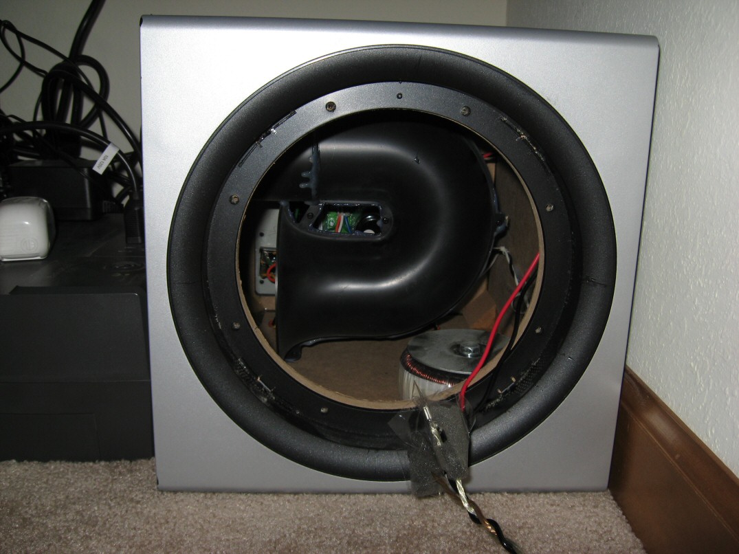
Hi Jseaber, im trying to take out the woofer and stuff in some polyfill into the box. But i cant take the woofer out~
1) I have remove the front grill
2) I have unscrew the 8 screws around the woofer
and Im stuck here…. what should i do next? or can you show me a video tutorial of it? thanks ^^
Just pry the woofer out after the screws are removed. There is some gasketing that the woofer sticks to, but it should pry free pretty easily.