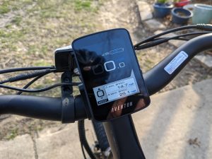
Aventon Pace 500 – Installing Throttle on Demand Controller Upgrade
I was excited to see Aventon’s Throttle on Demand Controller and new BC 280 Display. The Pace 500 has been awesome for the past 3...
I was excited to see Aventon’s Throttle on Demand Controller and new BC 280 Display. The Pace 500 has been awesome for the past 3...
There is no excerpt because this is a protected post.
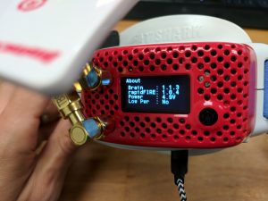
ImmersionRC’s rapidFIRE module is fantastic in High Power mode. Alas, the L1 mod worked about 80% of the time on my Fat Shark HD3’s. Here’s a particularly...
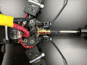
After the first 60 battery packs on the Rooster, I’ve learned a few costly lessons in keeping a mini-quad in the sky. Always use TWO Battery...
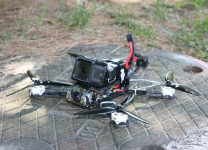
Nurk’s 2017 “Flight of the Year” hooked me on FPV drones. Not a DJI drone packed with idiot proof sensors, but a high speed drone in...
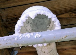
Jotting down notes for myself, as this is the third year in a row our furnace has failed during freezing weather. My wife and I...